Español
 عربى
 русский
Content
- 1 What a Copper Fiber Composite Cable Really Contains
- 2 Where Copper Fiber Composite Cable Makes Sense and Where It Does Not
- 3 The Commercial Case: Labor, Pathways, and Total Installed Cost
- 4 Specifying the Cable: Copper, Fiber, Jacket, and Construction
- 5 Voltage Separation and Safety: The Rule That Cannot Be Engineered Around
- 6 Termination, Polarity, and Test Planning
- 7 Sourcing Copper Fiber Composite Cable from a Manufacturer
- 8 Field Installation Sequence That Reduces Rework
- 9 Quality Checks, Acceptance, and Lifecycle Maintenance
- 10 Common Buying Mistakes and How to Avoid Them
- 11 FAQ about Copper Fiber Composite Cable
- 11.1 What is a copper fiber composite cable?
- 11.2 Is composite cable the same as hybrid cable?
- 11.3 Can a copper fiber composite cable carry power and fiber in one jacket?
- 11.4 How do I choose the fiber count and copper category?
- 11.5 Can composite cable be field terminated?
- 11.6 What should I ask a manufacturer or supplier before ordering?
- 11.7 How is a composite cable tested after installation?
- 12 Next Step: Plan the Route, Then Choose the Components
A facilities team plans a single new route from a ground-floor telecommunications room to a rooftop equipment area. The original design calls for one Cat 6A copper run and one 12-strand single-mode fiber run. The pathway is tight, the conduit is already crowded, and every additional pull adds labor, firestop work, and coordination time. A copper fiber composite cable looks like the obvious answer: one jacket, one pull, fewer route surveys. The useful conclusion is more specific. A copper fiber composite cable can reduce pathway pressure and installation time, but only when the design resolves voltage separation, fiber termination, bend radius, jacket rating, and acceptance testing before the cable is ordered.
The cable itself is not a universal replacement for separate copper and fiber systems. It is a construction choice that bundles copper conductors and optical fibers under one overall jacket, or sometimes under one assembly with separate sub-cables. That bundling changes the commercial and physical planning process. It does not remove the need to design the copper link, the fiber link, and the safety requirements as separate systems that happen to share a route.
The right composite cable decision starts with the route constraint and ends with a tested, documented link, not with a lower cable price alone.
What a Copper Fiber Composite Cable Really Contains
A copper fiber composite cable combines two transmission media in one assembly. The copper part may be a twisted-pair construction for Ethernet or PoE, a small conductor pair for power or control, or another copper configuration agreed with the project. The fiber part may be multimode or single-mode, tight-buffered or loose-tube, and may include a few strands or a high count for backbone use. The jacket may be riser-rated, plenum-rated, low-smoke zero-halogen, UV-resistant, armored, or built for direct burial. Those choices matter more than the label on the drum.
The term “composite” is used in different ways in the market. Some suppliers mean a true hybrid cable with copper and fiber under one overall jacket. Others mean separate copper and fiber sub-cables joined by a common sheath or binding. A few use the term for a bundled assembly that separates at each end into copper and fiber legs. For a buyer, the first question is not “Is it composite?” but “What is the exact construction, and how does it terminate?” The answer should appear on the datasheet, not only in a sales conversation.
Construction details that change the purchase
| Construction area | Confirm on the datasheet | Why it affects the project |
|---|---|---|
| Copper conductors | Pair count, AWG, solid or stranded, category, shield type, and rated use for PoE or power | Determines copper link performance, termination method, and whether the cable suits the active equipment |
| Fiber strands | Multimode or single-mode, OM3, OM4, OS2, strand count, buffer type, and color coding | Sets distance, connector choice, splice plan, and spare capacity for future growth |
| Overall jacket | Riser, plenum, LSZH, UV, oil resistance, burial rating, and temperature range | Controls where the cable can be installed and which local code requirements apply |
| Strength and protection | Armor, water blocking, rip cords, tensile limit, crush resistance, and minimum bend radius | Affects pulling tension, support spacing, repair options, and long-term reliability |
| Termination format | Field-terminated, factory pre-terminated, breakout length, fan-out, and connector type | Changes labor, test method, lead time, and the amount of on-site craft skill required |
A common mistake is to compare a composite cable with a standard copper cable and a standard fiber cable using only the cable cost line. That comparison hides the real differences. A composite construction may carry a material premium, but it can remove a second pull, a second set of supports, a second permit review in a congested pathway, and a second round of firestop inspection. On the other hand, it can add a fan-out enclosure, hybrid connector work, or a longer factory lead time. The correct comparison is installed cost and risk, not reel price.
Ask for the full construction and termination drawing before comparing prices, because two cables described as composite can behave like different products on site.
Where Copper Fiber Composite Cable Makes Sense and Where It Does Not
Composite cable is most useful when the route is the hard part. That includes a congested riser, a long exterior run to a small equipment cabinet, a rooftop radio or camera location, an industrial cell with limited conduit space, or a building upgrade where adding a second pathway would disrupt finished spaces. In those cases, pulling one assembly can reduce labor hours, scaffold time, and the number of wall penetrations. The value comes from the route, not from the idea that hybrid cable is automatically more advanced.
It can also help when a single project team controls both copper and fiber installation. One pull, one label scheme, one firestop detail, and one inspection sequence can simplify coordination. That is especially useful for a campus edge cabinet, a distributed antenna location, a security camera pole, or a small data room that needs both a copper service link and a fiber uplink. The cable becomes a route strategy rather than a product category.
Good candidates
- Equipment rooms and cabinets where a copper access link and a fiber uplink share the same path.
- Outdoor or industrial routes where one jacket, armor, or UV resistance reduces separate cable management.
- Retrofit projects with limited conduit fill, short installation windows, or occupied building constraints.
- Remote cabinets that need a copper service connection and a fiber backbone connection from one pull.
- Projects where factory pre-termination can be measured, verified, and protected before shipment.
Poor candidates
- Routes where copper power and communications circuits must be separated by code, and the composite construction cannot satisfy that separation.
- Projects where the copper and fiber endpoints are far apart and a single breakout would create messy service loops or excessive fan-out length.
- Buildings where local inspection authorities have not accepted the proposed jacket rating or hybrid assembly for the intended space.
- Small one-off jobs where the cost of a special order, factory termination, and extra testing exceeds the labor saved.
- Installations where future fiber growth is likely and a fixed composite design would lock the route into a low strand count.
The practical test is simple. Draw the route, mark the copper endpoint, mark the fiber endpoint, and mark where the two media separate. If the separation point is close to both endpoints and the jacket rating fits the space, a composite cable is worth pricing. If the separation point is awkward, or if the copper circuit needs a voltage separation that the assembly cannot provide, separate cables are often the cleaner design.
Composite cable is a route solution first; use it where one path is genuinely valuable and where the breakout and code requirements are already solved.
The Commercial Case: Labor, Pathways, and Total Installed Cost
On many projects, the labor to install a second cable exceeds the material difference between separate cables and a composite assembly. The saving appears in several places: fewer pulls, fewer cable supports, less conduit fill, fewer wall or floor penetrations, less firestop work, and shorter access equipment rental. The saving is not guaranteed. A composite cable may need a larger bend radius, a special breakout enclosure, hybrid connectors, or a factory termination that must be measured before walls are closed.
The chart below is an illustrative planning aid, not a price list. It compares relative installation effort for common route strategies. Actual results depend on pathway length, labor rates, local code, cable diameter, termination method, and the number of tested links.
Relative installation effort by route strategy
Illustrative planning index. Actual labor depends on route, code, and termination method.
The chart shows why a composite cable should not be sold as an automatic saving. Field termination can be practical when the installer has the right tools and the breakout point is accessible. Factory pre-termination can reduce site labor, but it shifts risk to measurement, packaging, and protection during the pull. Hybrid connectors can simplify the endpoint, yet they may add test adapters and spare-part complexity. A project team should compare those options against the actual route and the skill of the installation crew.
For a B2B buyer, the strongest commercial case usually appears when the route is difficult and the project schedule is tight. A hospital corridor, an operating factory, or an occupied office may cost far more to open twice than to install one composite assembly correctly. In an open new-build with wide trays and easy access, separate copper and fiber cables can remain the simpler and more flexible choice. The decision should follow the route and the acceptance plan.
Simante’s product structure supports this kind of comparison because the copper and fiber sides are planned as separate systems that meet at the rack. A copper link can be terminated on a Cat 6A patch panel while the fiber side lands on a fiber optical patch panel. The composite cable is then evaluated as a shared pathway with two distinct termination systems, which is the correct way to price it.
Price the composite route against the full installed cost of two separate routes, including terminations, testing, firestop, and schedule risk.
Specifying the Cable: Copper, Fiber, Jacket, and Construction
A useful specification begins with the active equipment, not with the cable catalog. On the copper side, confirm the category, conductor size, pair count, and PoE requirement. On the fiber side, confirm the fiber type, strand count, connector type, and loss budget. Then confirm the jacket rating and the installation environment. The composite assembly must satisfy both sides at once, so a change on one side can affect the diameter, bend radius, and termination plan on the other.
Match copper performance to the active equipment
A copper fiber composite cable may carry Cat 5e, Cat 6, or Cat 6A copper pairs, or it may use a smaller conductor for power or control. The category should match the link length and the network equipment. If the copper link is intended for PoE, check the conductor size, temperature rise, bundle size, and the manufacturer’s current-carrying guidance. A cable that performs well as a short patch link may not be suitable for a long PoE run in a warm ceiling void.
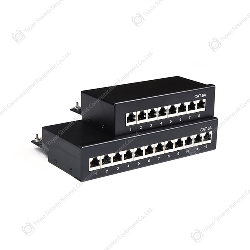
At the rack end, the copper pairs still need a proper termination point. A Cat 6A patch panel gives the installer a defined interface for testing and administration, even when the cable arriving at the rack is a composite assembly. The patch panel choice should follow the copper category and the number of ports, not the fact that the cable is hybrid.
Do not let fiber count be an afterthought
Fiber count is often the first thing cut to hit a price target, and it is often the first thing the project regrets. A composite cable with two fiber strands may be enough for a single uplink today, but it leaves little room for a second path, a split, or a future device. For a campus edge cabinet or a rooftop installation, a small increase in strand count can be far cheaper than a second pull later. The fiber type also matters. Multimode may suit a short building backbone, while single-mode may be better for a long exterior route or a campus connection.
Bend radius deserves attention because the composite assembly is usually stiffer and larger than either cable alone. The minimum bend radius should be stated for the installed condition, not only for the factory reel. Pulling tension should be stated for the assembly, and the installer should know which strength member carries the load. If the cable is armored, the armor adds protection but also changes weight, bend radius, and grounding requirements.
Jacket and environment
| Project condition | What to verify | Practical effect |
|---|---|---|
| Indoor plenum space | Plenum rating, smoke and flame performance, listing | May limit acceptable jacket compounds and require documentation for inspection |
| Riser or shaft | Riser rating, support intervals, vertical load | Affects clamping, strain relief, and the maximum unsupported height |
| Outdoor route | UV resistance, water blocking, temperature range, optional armor | Changes jacket material, gel or dry construction, and long-term maintenance |
| Industrial area | Oil resistance, crush resistance, EMI environment, grounding | May require shielding, armor, or a different separation plan |
| Factory pre-termination | Breakout length, fan-out protection, connector type, test report | Shifts labor to the factory but requires accurate route measurement |
A specification that lists only “composite fiber and copper cable” is too loose. It should state the copper category, pair count, fiber type, strand count, jacket rating, armor or shield requirement, maximum diameter, minimum bend radius, tensile limit, and termination format. That level of detail reduces the chance that two suppliers quote assemblies that look similar but cannot be installed with the same supports, connectors, or test plan.
Specify the copper link, the fiber link, and the shared jacket as three separate performance areas, then confirm that the composite assembly satisfies all three.
Voltage Separation and Safety: The Rule That Cannot Be Engineered Around
A composite cable that contains copper is not a nonconductive fiber cable. It carries conductive parts, and those parts may be connected to network equipment, PoE sources, control circuits, or power. That changes the safety review. The project must determine whether the copper conductors are classified as communications circuits, remote power, Class 2, Class 3, or another circuit type under the applicable local code. The jacket and assembly must be listed and rated for the space where it is installed.
Voltage separation is often the point where a promising composite design fails. If the copper pair is intended to carry power alongside communications, the installer cannot simply treat the whole assembly as low-voltage cable. Separation from other power circuits, conduit fill, heat rise, fault current, and grounding may all apply. The fact that the fiber is immune to electromagnetic interference does not remove the copper safety requirement. The fiber may be unaffected, but the copper conductor still needs a compliant installation.
Questions for the electrical and cabling designer
- What circuit classification applies to the copper conductors in the composite assembly?
- Does the jacket rating match the plenum, riser, or general-purpose space?
- Is the cable listed for the intended use, and is the listing document available?
- What separation is required from power circuits, motors, transformers, or other EMI sources?
- Does the copper shield or armor require bonding, and at which end?
- Does the bundle size or ambient temperature reduce the allowed current for PoE?
These questions should be answered before the cable is purchased, not after the first inspection. A supplier can provide the cable construction, jacket rating, conductor size, and test data, but the authority having jurisdiction and the project designer determine acceptance. A responsible manufacturer will not promise that a single composite construction fits every code environment. A useful supplier will help the buyer organize the technical data so the designer can make a clear decision.
Treat the copper in a composite cable as a conductive circuit first and as part of a hybrid assembly second, because safety acceptance is not a marketing decision.
Termination, Polarity, and Test Planning
The endpoint is where a composite cable earns or loses its value. At the copper end, the pairs need to be terminated, labeled, and tested to the selected category. At the fiber end, the strands need connectors, splices, or a fan-out that protects the fiber and keeps polarity correct. If the two media separate at a breakout point, that point needs a enclosure, strain relief, and enough service loop for maintenance. A messy breakout can erase the labor saved by the single pull.
Fiber polarity is easy to overlook when the cable is ordered as one assembly. The installer should know whether the fiber is intended for a duplex link, a parallel optical link, or a splice-only backbone. The connector type should match the patch panel and the active equipment. If the cable is factory pre-terminated, the breakout length and labeling should be checked against the route before shipment. If it is field-terminated, the crew needs the right cleaving, splicing, and connector tools.
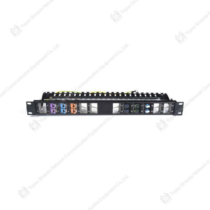
At the fiber rack end, a proper fiber optical patch panel provides a protected interface for termination, splicing, and administration. It also gives the project a clean separation between the composite cable breakout and the fiber patch cords that connect to the switch. That separation matters for testing and for future maintenance.
Acceptance testing that matches the assembly
Copper testing should follow the selected category and the project standard. The report should include length, wire map, insertion loss, return loss, and other parameters required by the test specification. Fiber testing should include optical loss, polarity, and end-face inspection. If the route uses splices or multiple connector pairs, the loss budget should account for them. A composite cable does not change the test limits for each medium, but it does change the test schedule because both media share one pull and one route.
Test planning should start before installation. The project team should decide which links will be tested, what test equipment will be used, how the results will be labeled, and who will accept the fiber end-faces. If factory pre-termination is used, the factory report should be compared with the field test. If field termination is used, the first few links should be tested early so a bad termination method does not repeat across the whole route.
Plan copper certification and fiber loss testing together, because one shared pull still creates two separate acceptance records.
Sourcing Copper Fiber Composite Cable from a Manufacturer
Buying a composite cable is not the same as buying a standard reel from stock. The buyer should know who controls the copper construction, who controls the fiber, and who performs the final assembly and test. A manufacturer with both copper and fiber product experience can often coordinate the termination and documentation more cleanly than a trader that buys two finished cables and binds them together. That does not mean every manufacturer is the right fit, but it does mean the sourcing questions should go beyond price per meter.
A wholesaler or distributor may be a good choice for a small project that needs a standard construction and a short lead time. A manufacturer is usually the better route when the project needs a custom strand count, a specific breakout length, factory pre-termination, private labeling, or a test report tied to the production batch. For export projects, confirm the documentation language, packaging, and delivery terms before the order is placed.
Procurement checklist
- Confirm the exact construction drawing, including copper category, fiber type, strand count, jacket, armor, and diameter.
- Ask for a sample or a short length for connector fit, bend radius, and jacket handling checks.
- Confirm minimum order quantity, production lead time, and whether custom lengths are available.
- Request test data for copper and fiber, and confirm whether the report is batch-specific or generic.
- Check packing, reel size, pulling direction, and end protection for export shipment.
- Confirm labeling, language, and documentation required for the project and the customs process.
- Agree on the acceptance criteria for pre-terminated ends, breakout lengths, and fiber end-face quality.
The sourcing conversation should also cover change control. If the fiber count changes, does the cable diameter change? If the jacket changes from riser to plenum, does the lead time change? If the copper category changes from Cat 6 to Cat 6A, does the termination method change? A supplier that can answer those questions quickly is easier to work with than one that treats every inquiry as a new product.
Source the composite cable as an engineered assembly with drawings, test data, and change control, not as a commodity reel with a hybrid label.
Field Installation Sequence That Reduces Rework
A composite cable is larger and heavier than a single copper cable, so the installation sequence should be planned before the first pull. Survey the route for bend radius, support spacing, access points, and separation from power. Confirm that the pulling tension will be applied to the correct strength member. Identify where the cable will separate and how the breakout will be supported. If the cable is pre-terminated, protect the connectors with a pulling sock or a suitable protector and confirm that the route can accept the connector profile.
Cable management at the rack is not a cosmetic detail. A composite assembly creates a transition point where copper pairs and fiber strands leave the shared jacket. That transition needs strain relief and a clear bend radius. A cable manager can keep the copper and fiber legs separated, support service loops, and prevent the breakout from hanging on the connectors. Good management also makes future testing and replacement easier.
 Rack Cable Managers for Structured Cabling TransitionsOrganize and secure copper and fiber legs at rack breakouts, with options for strain relief, bend-radius support, and easier maintenance.View Product →
Installation steps
- Walk the route and mark every bend, penetration, support point, and separation point.
- Verify conduit fill, tray capacity, and the minimum bend radius of the full assembly.
- Set up pulling equipment so tension is controlled and monitored, not estimated by feel.
- Use suitable lubricant only when the jacket and the pathway are compatible with it.
- Support the cable at the specified intervals and avoid tight zip ties or sharp edges.
- Maintain separation from power circuits and bond shields or armor as the design requires.
- Form service loops at the breakout and at each rack without exceeding the bend radius.
- Label the cable, the breakout, and both media ends before the cable is dressed into final position.
- Firestop every penetration and record the installation details for the acceptance package.
Rework usually starts with a small assumption. The crew assumes the breakout can sit in a 100 mm space, but the fan-out needs more. The designer assumes the cable can turn a 90-degree corner inside a shallow tray, but the assembly cannot. The installer assumes the pre-terminated connector will pass through a 25 mm hole, but it will not. These are not cable failures. They are planning failures. A short mock-up at the breakout and a route walk with the actual cable diameter can expose them before the pull.
Install the breakout as carefully as the main pull, because the shared jacket creates a transition point that needs support, radius control, and labeling.
Quality Checks, Acceptance, and Lifecycle Maintenance
Acceptance should confirm that the installed composite cable meets the design for both media. For copper, that means category testing with pass margins that leave room for temperature and aging. For fiber, that means loss testing with connector end-face inspection and polarity verification. The documentation should include cable routes, breakout locations, port mapping, test results, and photos of the rack and breakout. That package is useful during handover and even more useful when a link fails three years later.
Maintenance planning should account for the shared route. If the copper link fails, the technician needs to access the copper termination without disturbing the fiber. If a fiber strand fails, the technician needs a splice or repair plan that does not put tension on the copper pairs. A spare fiber strand or a spare copper pair can reduce downtime, but only if the documentation shows where it terminates. A composite cable with no spare capacity and no records can turn a simple fault into a full route replacement.
Inspect the jacket at each support point and penetration after the pull. Look for flattening, abrasion, or tight bend marks. Check the breakout for strain relief and fiber bend radius. Confirm that the copper pairs are not under tension at the termination and that the fiber fan-out is protected. These checks do not replace formal testing, but they catch mechanical problems that a tester may not explain.
Hand over the composite route with separate copper and fiber records, plus breakout photos and a spare-capacity plan for future maintenance.
Common Buying Mistakes and How to Avoid Them
Most composite cable problems appear before the cable arrives. They are specification, sourcing, and planning errors rather than manufacturing defects. The following mistakes are common enough to check on every project.
- Treating the composite cable as a drop-in replacement for two separate cables without checking voltage separation and jacket rating.
- Choosing the fiber count by current device count only, with no spare strand for testing or future growth.
- Ordering pre-terminated cable before the route is measured and the pulling path is confirmed.
- Comparing cable price per meter while ignoring breakout enclosures, hybrid connectors, test adapters, and schedule risk.
- Using a copper category that does not match the active equipment or the PoE load.
- Ignoring the minimum bend radius of the full assembly and planning the route around the copper cable alone.
- Accepting a generic test report instead of batch-specific copper and fiber data.
- Leaving the breakout unsupported, so the connectors carry the weight of the cable.
A buyer can avoid most of these mistakes with a one-page decision record. It should state the route, the copper link, the fiber link, the jacket rating, the separation requirement, the termination format, the test plan, and the responsible person for each item. When a supplier quote arrives, the buyer can compare it with that record instead of comparing only the price. That simple discipline is more useful than a long checklist that no one reads.
Most costly composite cable failures are planning failures, so resolve the route, code, termination, and test plan before issuing the purchase order.
FAQ about Copper Fiber Composite Cable
What is a copper fiber composite cable?
It is a cable assembly that contains both copper conductors and optical fiber strands in one overall construction. The copper may be a twisted-pair Ethernet cable or a power and control conductor. The fiber may be multimode or single-mode. The assembly may use one jacket over both media or separate sub-cables bound together. The exact construction should be confirmed on the datasheet.
Is composite cable the same as hybrid cable?
The terms are often used interchangeably, but the market is not strict. Some suppliers use hybrid for a true copper and fiber assembly, while others use composite for a bundled construction. The buyer should ask for a cross-section drawing and the termination format rather than rely on the name. The drawing is the reliable description.
Can a copper fiber composite cable carry power and fiber in one jacket?
It can be built with copper conductors for power or PoE, but that does not remove the applicable electrical code requirements. The copper part must be rated for the circuit, the jacket must suit the space, and separation from other power circuits may still apply. The designer and the authority having jurisdiction should confirm acceptance before the cable is ordered.
How do I choose the fiber count and copper category?
Start with the active equipment and the link length. Choose the copper category from the network speed, PoE load, and test standard. Choose the fiber type from the distance and the optical budget. Then add spare capacity for testing, future growth, or a second path. A small increase in strand count or pair count is often cheaper than a second pull later.
Can composite cable be field terminated?
Yes, but field termination requires the right tools and a clear breakout plan. Copper pairs need category-compliant termination and testing. Fiber strands need connectors or splices, protection, and loss testing. If the route is difficult or the project schedule is tight, factory pre-termination may be better, provided the route is measured accurately and the connectors are protected during the pull.
What should I ask a manufacturer or supplier before ordering?
Ask for the construction drawing, copper and fiber test data, jacket rating, minimum bend radius, tensile limit, termination options, minimum order quantity, lead time, packing method, and change-control process. For export projects, confirm labeling and documentation language. A manufacturer that can answer these questions clearly is easier to qualify than one that offers only a price per meter.
How is a composite cable tested after installation?
The copper side is tested to the selected category using a qualified tester and recorded link results. The fiber side is tested for optical loss, polarity, and end-face condition. The two test records should be linked to the same cable ID and breakout location. A shared pull does not mean a shared test result, because copper and fiber have different acceptance criteria.
Use the FAQ as a pre-order review: if the construction, code path, termination, and test answers are unclear, the cable is not ready to buy.
Next Step: Plan the Route, Then Choose the Components
A copper fiber composite cable can be a practical choice for a congested pathway, a remote cabinet, or a retrofit where a second pull would create disruption. It can also be the wrong choice when voltage separation, breakout space, or fiber termination has not been resolved. The difference is not the cable alone. It is the design discipline around the cable: a route drawing, a copper specification, a fiber specification, a jacket rating, a termination plan, and an acceptance test that covers both media.
Simante manufactures structured cabling components for copper and fiber systems, including keystone jacks, patch panels, faceplates, surface mount boxes, cable managers, and fiber optical patch panels. For a composite cable project, that matters at the transition points. The copper link needs a defined rack interface. The fiber link needs a protected patch panel interface. The breakout needs cable management. A manufacturer that understands those interfaces can help a buyer compare a composite route with a conventional two-cable route on a more realistic basis.
Use these reference pages to continue the design review:
- Review Simante’s manufacturing and quality overview before requesting a custom composite assembly or a matched copper and fiber component set.
- Read the guide to core components of a structured cabling system to map the copper, fiber, patching, and cable management interfaces around the shared route.
The practical next step is to draw the route and mark the separation point. Then list the copper category, fiber type, strand count, jacket rating, termination format, and test method. With that one-page plan, a buyer can approach a manufacturer, supplier, or wholesaler with clear questions and compare responses on the same technical basis. That approach reduces the chance that a promising hybrid route becomes an expensive repair.
Choose the composite cable only after the route, code path, breakout, and two-media test plan are documented and accepted by the project team.