Español
 عربى
عربى русский
Content
- 1 Keystone Jacks: The Connection Point That Defines Channel Performance
- 2 Performance Comparison: Keystone Jack Categories — Horizontal Bar Chart
- 3 Patch Panels: The Central Termination Hub of Any Structured Cabling System
- 4 Patch Panel Port Density vs. Rack Space — Column Chart
- 5 Fiber Optic Cabling: The High-Bandwidth Backbone for Data Center and Campus Networks
- 6 Fiber vs. Copper Bandwidth Over Distance — Line Chart
- 7 Cable Management Rack and Server Rack Accessories: Protecting Performance Through Physical Organization
- 8 RJ45 Connectors: Field Termination Quality Controls Network Channel Performance
- 9 Structured Cabling System Component Radar — Performance Profile
- 10 Designing a Complete Structured Cabling Solution: System Integration Principles
- 11 Structured Cabling Deployment Growth by Segment (2020–2024)
- 12 About Yuyao Simante Network Communication Equipment Co., Ltd.
- 13 Frequently Asked Questions
The structured cabling products that most reliably support high-speed networks are Cat6/Cat6A keystone jacks, fiber optic cabling assemblies, ethernet patch panels, high-density cable management racks, and properly rated RJ45 connectors. Together, these components form a complete structured wiring system capable of sustaining 10 Gbps throughput over copper and 100 Gbps or beyond over fiber — the bandwidth benchmarks increasingly demanded by modern data centers, commercial office builds, and enterprise campus networks. Rather than relying on a single component, high-speed network performance depends on every element of the structured cabling solution being correctly specified, installed, and tested to recognized standards such as ANSI/TIA-568, ISO/IEC 11801, and EN 50173. The sections below break down each critical product category and explain exactly what to look for when building or upgrading a high-speed structured cabling system.
Keystone Jacks: The Connection Point That Defines Channel Performance
The keystone jack is the termination interface between structured cabling and end-user devices, and it plays a disproportionate role in overall channel performance. A poorly rated keystone jack can degrade an otherwise excellent cable run — introducing return loss, near-end crosstalk (NEXT), and impedance mismatches that limit throughput well below what the cable itself could support.
Keystone Jack Cat6 and Cat6A for 10GbE Applications
For networks targeting 10 Gigabit Ethernet (10GbE) over copper, keystone jack Cat6A (Augmented Category 6) is the minimum recommended component. Cat6A keystone jacks are engineered to perform up to 500 MHz — double the 250 MHz rating of standard Cat6 — which is required to maintain channel headroom at 10GbE over runs of up to 100 meters. Standard keystone jack Cat6 supports 10GbE only to approximately 37–55 meters depending on alien crosstalk conditions, making it suitable for shorter-reach applications. Key selection criteria for keystone jacks include:
- TIA-568 or ISO/IEC 11801 category certification (Cat6 or Cat6A minimum for 10GbE)
- 110-type or tool-less IDC termination compatible with the cable's conductor gauge (24 AWG or 23 AWG)
- Shielded (STP) or unshielded (UTP) configuration matched to the cable type in the installation
- Net keystone jack formats for use with modular patch panels and faceplates
- Durability ratings of 750+ mating cycles for high-use access point locations
Leading keystone jack manufacturers offer both standard and angled formats to accommodate different faceplate orientations and wall box depths. Angled keystone jacks reduce cable bend radius stress at the termination point — an important consideration in dense commercial network cabling deployments where multiple ports share a compact enclosure. RJ45 keystone jack modules should be tested as part of the complete channel (jack, patch cord, cable, and patch panel port) to verify compliance, not tested in isolation.
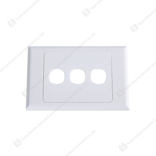
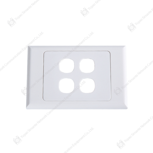
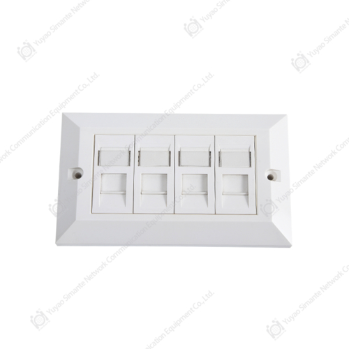
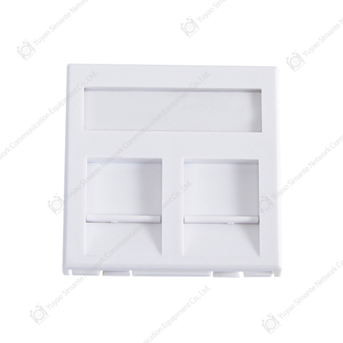
Faceplates and Network Faceplates for Workspace Outlets
The faceplate secures keystone jacks at the work area outlet (WAO) and contributes to both physical protection and cable management quality. Faceplate manufacturers offer single, dual, four-port, and six-port configurations compatible with standard keystone module formats. A network face plate with a dust-shutter design protects unused ports from contamination — a detail that matters in industrial environments or exposed installation locations. Blank patch panel style faceplates with slide-in labels enable clear port identification without permanent marking. Faceplate RJ45 assemblies combine the faceplate and pre-terminated jack as a single unit, reducing field termination time in large commercial network cabling projects.
Performance Comparison: Keystone Jack Categories — Horizontal Bar Chart
The chart below compares three keystone jack categories across four performance dimensions — maximum frequency, supported channel length at 10GbE, NEXT headroom, and return loss margin — all expressed as normalized scores out of 100. Cat6A leads across all four metrics, making it the preferred choice for high-speed structured cabling installations targeting 10GbE and above. Cat6 remains a practical option for shorter runs and lower-bandwidth applications where the full Cat6A specification is not required. Cat5e is included as a reference baseline to illustrate the performance gap that upgrading to Cat6 or Cat6A delivers, particularly in frequency headroom and alien crosstalk rejection. Procurement teams planning network upgrades should note that the per-port cost differential between Cat6 and Cat6A keystone jacks is typically modest — often less than 20% — making Cat6A the more future-proof selection for new builds.
Patch Panels: The Central Termination Hub of Any Structured Cabling System
The patch panel is the backbone termination point in every telecom room, server room, or data center cabling layout. It aggregates horizontal cable runs from work area outlets and provides a flexible, manageable cross-connection point for routing network traffic between switches, servers, and end devices. Without a properly specified ethernet patch panel, moves, adds, and changes (MACs) in a live network require re-terminating permanent links — a time-consuming and error-prone process that structured cabling standards are specifically designed to eliminate.
Cat6 Patch Panel Selection for High-Density Environments
A cat6 patch panel rated to TIA-568-C.2 or ISO/IEC 11801 Class E delivers the 250 MHz channel performance needed for Gigabit Ethernet across full 100-meter permanent link distances. For 10GbE environments, a cat6 patch panel rated for Cat6A (500 MHz, Class EA) is required. High-density formats — patch panel units offering 24, 48, or even 96 ports in a 1U or 2U rack space — are favored in data center cabling environments where rack real estate is at a premium. Key specifications to evaluate include:
- Port density: 24-port 1U is the standard for commercial network cabling; 48-port 1U panels serve data center cabling applications with higher port counts per rack unit
- Termination type: 110-type IDC punchdown (fixed panel) or toolless keystone-module loaded panels for field-swappable ports
- Shielding: Shielded patch panels with individually shielded ports for STP cable environments; full metal housing for EMI-sensitive data center locations
- Rear cable management: Integrated or snap-on cable management bars to maintain bend radius on terminated cable tails
- Labeling system: Built-in label strips or blank patch panel insert slots for clear port identification
Reputable patch panel manufacturers supply fully tested channel compliance reports and channel simulation data demonstrating that the patch panel port contributes within the allocated component insertion loss and crosstalk budget for the overall channel. Selecting a panel without this documentation introduces significant risk of channel non-compliance — particularly in high-density deployments where even marginal component shortfalls aggregate into measurable throughput degradation.
Patch Panel Port Density vs. Rack Space — Column Chart
The clustered bar chart below compares four common ethernet patch panel configurations by two metrics: port count per panel and rack units consumed. The relationship between density and rack space directly affects total infrastructure cost in data center cabling environments where each rack unit has measurable real estate value. The 48-port 1U format delivers the best port density per rack unit but may require additional front-of-rack cable management to prevent congestion. The 24-port 2U format allows greater cable management space per port and is frequently preferred in commercial network cabling builds where technician accessibility and neat appearance are priorities. Angled patch panels (not shown separately) occupy the same U-space as flat panels but route patch cords to the side, reducing the depth of cable bundles in front of the panel — a useful option in deep data center cabling racks with limited front-to-back airflow clearance.
Fiber Optic Cabling: The High-Bandwidth Backbone for Data Center and Campus Networks
While copper-based structured cabling handles the majority of horizontal work area connections, fiber optic cabling dominates backbone, inter-building, and high-speed data center cabling links where distance and bandwidth requirements exceed what copper can practically deliver. A properly designed structured cabling solution integrates both media types: copper for the horizontal subsystem, and fiber for backbone and equipment room interconnects.
Multimode vs. Single-Mode Fiber in Structured Cabling Systems
OM3 and OM4 multimode fiber supports 10GbE to distances of 300m and 400m respectively, and OM5 extends wideband multimode performance to emerging 40G and 100G applications using short-wave division multiplexing (SWDM). For inter-building runs exceeding 500m, or for links requiring 100GbE, 400GbE, or beyond, single-mode OS2 fiber is the correct choice. In modern data center cabling designs, pre-terminated fiber optic cabling assemblies — MPO/MTP trunk cables with breakout cassettes — dramatically reduce installation time and eliminate field-polishing errors. Key fiber selection criteria include:
- Fiber type: OM3, OM4, OM5 multimode or OS2 single-mode — matched to distance and bandwidth requirements
- Connector type: LC duplex for most server and switch connections; MPO-12 or MPO-24 for high-density data center parallel optics applications
- Polish type: UPC (Ultra Physical Contact) for single-mode; APC (Angled Physical Contact) for passive optical networks with stringent return loss requirements
- Insertion loss budget: Verify end-to-end channel insertion loss stays within the transceiver's receive sensitivity budget at the target data rate
- Fire rating: LSZH (Low Smoke Zero Halogen) jackets for indoor plenum or riser runs in commercial buildings
Fiber vs. Copper Bandwidth Over Distance — Line Chart
The line chart below illustrates supported data rates at increasing distances for four common structured cabling media types: Cat6 copper, Cat6A copper, OM4 multimode fiber, and OS2 single-mode fiber. The performance gap between copper and fiber widens dramatically beyond 100 meters — the physical limit of copper horizontal cabling under any category rating. OM4 fiber sustains 10GbE to 400 meters and 40GbE to 150 meters, while OS2 single-mode supports 100GbE and beyond over distances measured in kilometers rather than meters. This contrast explains why large commercial network cabling projects and all serious data center cabling designs use fiber for backbone segments and reserve copper for the final horizontal run to the desktop or access point. Understanding this boundary — and specifying fiber optic cabling for all backbone segments from the outset — avoids the disruptive and expensive retrofitting that occurs when copper backbone installations hit their bandwidth ceiling.
Cable Management Rack and Server Rack Accessories: Protecting Performance Through Physical Organization
Even perfectly specified and terminated network cabling products will underperform if the physical cable plant is poorly managed. Exceeding the minimum bend radius of Cat6A UTP cable (typically 4× the cable outer diameter, or approximately 28–32mm) causes permanent deformation of the internal pair geometry — introducing impedance discontinuities and crosstalk that no amount of re-termination can correct. Proper cable management rack infrastructure prevents this by guiding cable through controlled routing paths at safe bend radii throughout the entire structured wiring system.
Essential Cable Management Components
A complete network cable management strategy for a data center or telecom room includes the following server rack accessories:
- 1U/2U horizontal cable managers: Finger-duct style rings guide patch cord runs between patch panels and switches, keeping front-of-rack cabling organized and accessible
- Vertical cable managers: Side-mounted 0U vertical managers route inter-rack cables through the full height of the cabinet without crossing active equipment — essential in high-density data center cabling layouts
- Raised floor or overhead cable tray: Segregated pathways for power and data cabling in larger commercial network cabling installations, preventing electromagnetic interference between high-current power feeds and signal cables
- Cable lacing bars and D-rings: Secure horizontal cable bundles in the rear of the rack at controlled bundle diameters that protect bend radius on both copper and fiber
- Velcro ties vs. zip ties: Re-adjustable velcro hook-and-loop fasteners are strongly preferred over permanent cable ties in structured cabling systems where MACs are frequent — zip ties cinched too tightly permanently deform cable pair twist geometry
| Component | Location in Rack | Primary Function | Rack Space Used |
|---|---|---|---|
| Horizontal Cable Manager | Front, between panels | Patch cord routing & bend radius | 1U or 2U per unit |
| Vertical Cable Manager | Side panels, 0U | Inter-rack backbone routing | 0U (side-mounted) |
| Cable Lacing Bar | Rear of rack | Horizontal cable bundling | 0U |
| D-Ring Cable Guide | Rear rack posts | Vertical cable runs, fiber protection | 0U |
| Cable Tray (overhead) | Above rack row | Inter-rack routing, power/data separation | Ceiling-mounted |
RJ45 Connectors: Field Termination Quality Controls Network Channel Performance
The RJ45 male connector is the field-terminated plug used on patch cords, equipment cords, and direct-connect assemblies. While it appears simple, the quality of RJ45 connector terminations is one of the most common sources of channel failures in structured cabling system installations. Inferior connectors — or correct connectors improperly crimped — introduce pair unbalance, return loss, and insertion loss failures that are difficult to trace without field test equipment.
Selecting the Right RJ45 Male Connector for Your Cable Type
Not all RJ45 male connectors are compatible with all cable types. The key compatibility factors are:
- Conductor configuration: Solid conductor cables (permanent link) require connectors with sharp IDC contacts designed for solid wire; stranded conductor cables (patch cords) require contacts designed for stranded wire — using the wrong type causes intermittent contact failures
- Cable OD compatibility: Cat6A cable outer diameters typically range from 7–9mm; verify the connector strain relief boot accommodates the cable OD without excessive compression or looseness
- Category rating: Use Cat6-rated or Cat6A-rated RJ45 male connector formats for high-speed networks — Cat5e connectors have wider slot tolerances that allow pair untwisting beyond Cat6 limits, degrading crosstalk performance
- Shielding: Shielded (STP/SFTP) connectors with 360° metal housing for shielded cable assemblies — ground continuity through the connector is essential for shielded network cabling products to deliver their EMI rejection benefit
- Gold contact plating thickness: 50 microinches (1.27 μm) gold plating is the standard for reliable contact performance over 750+ mating cycles in commercial structured cabling deployments
Leading RJ45 connector manufacturers supply connectors with integrated load bars or conductor guides that hold all eight conductors in precise position during crimping — a feature that significantly reduces pair-swap and open-pair termination errors compared to open-slot connector designs. Specifying these controlled-geometry rj45 connector formats is particularly valuable in field environments where technician termination technique varies.
Structured Cabling System Component Radar — Performance Profile
The radar chart below compares five core structured cabling system components across six performance attributes: Bandwidth Support, Physical Durability, Installation Speed, Scalability, Standards Compliance Range, and Cost Efficiency. Fiber optic cabling leads on bandwidth support and scalability but scores lower on cost efficiency and installation speed due to the specialist skills required for fiber handling and termination. Patch panels and keystone jacks score consistently across all attributes, reflecting their mature, well-standardized designs. Cable management components score highest on installation speed and durability — they add significant value at relatively low complexity. RJ45 connectors score highest on cost efficiency given their unit economics, though their performance contribution is highly sensitive to termination quality, which is reflected in their moderate standards compliance score when field-terminated rather than factory-assembled. Together, these components form the complete structured cabling solution that defines whether a network infrastructure can truly support high-speed operation over its intended service life.
Designing a Complete Structured Cabling Solution: System Integration Principles
A structured cabling solution performs as a system, not a collection of individual components. The ANSI/TIA-568 and ISO/IEC 11801 channel model defines performance limits for the entire end-to-end channel — from the equipment port on the switch through the patch cord, patch panel port, permanent link cable, keystone jack, and work area patch cord to the end device NIC. Each component contributes insertion loss, return loss, and crosstalk, and these contributions accumulate across the channel. The three principles that ensure system-level performance are:
- Component consistency: Use components from the same structured cabling system category throughout each channel — mixing Cat6A cable with Cat6 keystone jacks produces a Cat6 channel regardless of cable rating
- Channel testing: Test completed channels with a Tier 2 field tester capable of measuring all parameters required by TIA-568 or ISO/IEC 11801 for the target category — visual inspection alone cannot confirm electrical compliance
- Documentation: Record test results, cable identifiers, panel and port assignments, and as-built drawings — the structured wiring system documentation is as valuable as the physical installation for ongoing network management and troubleshooting
For commercial network cabling projects, specifying a systems warranty from the cabling manufacturer (typically 15–25 years covering both components and channel performance) provides the strongest long-term assurance. These warranties require all components — cable, connectors, patch panel, keystone jacks, and faceplates — to be from the same certified product family, and installation to be performed by an authorized contractor trained on that manufacturer's network cabling solution and termination procedures.
Structured Cabling Deployment Growth by Segment (2020–2024)
The stacked bar chart below illustrates the relative growth in structured cabling installation volume across three primary segments — enterprise commercial cabling, data center cabling, and industrial/manufacturing network cabling — from 2020 through 2024. Data center cabling has shown the most dramatic growth, driven by cloud computing infrastructure expansion, hyperscale facility builds, and the accelerating deployment of AI computing infrastructure requiring high-density 400GbE and emerging 800GbE interconnect. Enterprise commercial network cabling has grown steadily, supported by office modernization projects, Wi-Fi 6/6E access point deployments that require Cat6A horizontal cabling, and the retrofitting of older commercial buildings with modern structured wiring systems. Industrial network cabling is the smallest but fastest-growing segment by percentage, as manufacturing industries adopt Industrial Ethernet and IIoT architectures that require structured cabling solutions engineered for harsh environments with vibration, temperature variation, and electromagnetic interference.
About Yuyao Simante Network Communication Equipment Co., Ltd.
Yuyao Simante Network Communication Equipment Co., Ltd. is a professional manufacturer of network cabling solutions and optical fiber products, integrating design, development, sales, and service under one roof. In nearly 20 years of service, Simante has remained committed to meeting the needs of customers through deep technical expertise and delivering maximum value from the very first point of contact.
Based on a mature research and development system, the quality stability of Simante's structured cable products — including keystone jacks, patch panels, faceplates, and RJ45 connectors — is guaranteed at the design source. Simante employs more than 10 engineers and over 30 full-time technical personnel who continuously apply their expertise to improving quality and driving product updates across the complete range of structured cabling system components. This technical depth ensures that every product leaving the Simante facility meets the performance standards that modern structured cabling solutions demand.
Professional Manufacturing · Reliable Network Cabling Solutions
Frequently Asked Questions
Q1: What structured cabling products are needed for a 10GbE network?
A1: A 10GbE network over copper requires Cat6A cable, Cat6A keystone jacks, a Cat6A-rated patch panel, Cat6A patch cords, and Cat6A RJ45 connectors throughout. All components must be Cat6A (Class EA) rated and channel-tested to TIA-568-C.2 or ISO/IEC 11801 Class EA to ensure full 100-meter 10GbE performance.
Q2: What is the difference between a keystone jack and a patch panel port?
A2: A keystone jack is a modular termination interface installed at the work area outlet (faceplate or wall plate), while a patch panel port is the termination point in the equipment room where horizontal cable runs terminate. In modular patch panel designs, the patch panel port is itself loaded with a keystone jack module, making both components part of the same structured cabling product family.
Q3: Can I mix Cat6 and Cat6A components in the same channel?
A3: Technically you can, but the channel will only perform to the lowest-rated component. Mixing Cat6A cable with Cat6 jacks or patch panels results in a Cat6 channel — it will not achieve the 500 MHz, 10GbE-at-100m performance that Cat6A is specified to deliver. For consistent and certifiable performance, use matched components throughout each channel.
Q4: When should fiber optic cabling be used instead of copper in a structured cabling system?
A4: Fiber optic cabling should be used for all backbone links exceeding 100 meters, any link requiring 40GbE, 100GbE, or higher data rates, inter-building connections, and environments with high electromagnetic interference. In data center cabling, fiber is standard for all switch-to-switch and switch-to-server interconnects above 10GbE.
Q5: Why does cable management affect network performance?
A5: Exceeding the minimum bend radius of structured cabling permanently deforms the internal pair geometry, increasing crosstalk and return loss beyond category limits. Cable ties cinched too tightly cause similar compression damage. Proper cable management rack products — horizontal managers, D-rings, and lacing bars — protect cable geometry through controlled routing and appropriate bundling diameters.
Q6: What certifications should I look for from structured cabling product manufacturers?
A6: Look for TIA-568 category compliance (Cat6, Cat6A), ISO/IEC 11801 class compliance (Class E, Class EA), UL listing for fire safety, RoHS compliance for environmental regulations, and ETL or third-party lab verification of electrical performance. For systems warranties, verify that the manufacturer is recognized by an authorized channel certification program and provides documented test methodology for the warranted component family.