Español
 عربى
عربى русский
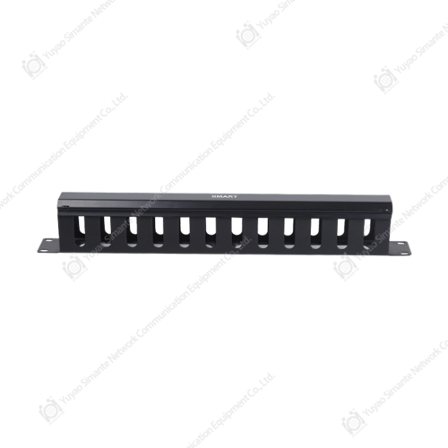
The horizontal wiring system is the physical link between the information point in the building and the floor wiring room. As the core aggregation node of the floor wiring room, the 24-port fiber optic patch panel is responsible for signal integration and centralized management. The optical fiber from each information point is laid to the floor wiring room through the pre-buried cable trough, bridge or exposed cable tube, and accurately connected to the corresponding port of the patch panel to form the physical topology of the fiber optic network in the floor. This centralized access method not only simplifies the wiring path, but also ensures the stability and maintainability of signal transmission through standardized port design.
As the connection medium between the horizontal wiring system and the patch panel, the fiber optic patch cord is plug-and-play through standardized interfaces such as LC/SC/MPO. Its duplex/simplex structure can adapt to different transmission requirements, and the armored/unarmored type can adapt to complex environments such as computer rooms and weak current wells. The patch cord adopts anti-bending low-loss optical fiber, and is equipped with a dust-proof tail sleeve with an identification label, which not only ensures that the link attenuation is ≤0.3dB/km, but also realizes visual link management through color coding. Maintenance personnel can quickly locate the fault point through the jumper mark to achieve link switching and redundant backup.
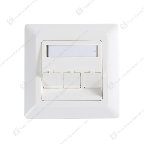
The work area wiring system realizes the physical connection between the terminal equipment and the horizontal wiring system through the information point. Taking the six categories of unshielded twisted pair as an example, its RJ45 crystal head is connected to the optical-electrical conversion equipment in the floor wiring room through the cable trough after being jumpered by the information module, and then connected to the 24-port fiber optic patch panel through the fiber optic patch panel. The link follows the TIA-568.2-D standard throughout, and the near-end crosstalk (NEXT) is ≥45dB, ensuring that the terminal equipment can stably access the Gigabit/10G network.
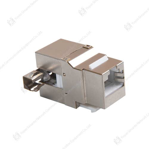
The 24-port fiber optic patch panel provides dynamic expansion capabilities for the work area equipment through the collaboration with the horizontal wiring system. When adding new terminal equipment, you only need to add cables at the information point end and access the free port of the patch panel through the horizontal wiring system to complete the physical layer expansion. Its 24-port design supports independent configuration of each port, which can not only carry the uplink link of the access layer switch, but also serve as a jumper node for the cross-floor optical cable to achieve flexible interconnection between the work area network and the core network.
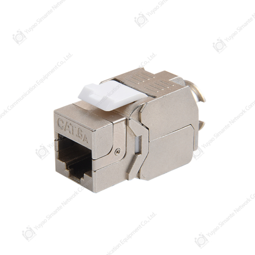
As the hub of the floor network signal, the 24-port fiber optic patch panel realizes link full life cycle monitoring through port-level management. Its integrated fiber optic adapter panel supports port status indicators, and with the intelligent electronic label system, it can display port numbers, access devices, link attenuation and other parameters in real time. Through the patch panel management software, managers can remotely generate topology maps and link test reports, shortening the fault location time from 2 hours of traditional manual troubleshooting to 5 minutes.