Español
 عربى
عربى русский
Content
- 1 Patch Panel vs Switch: The Direct Answer
- 2 What Is a Patch Panel and How Does It Work
- 3 What Is a Network Switch and How Does It Differ From a Patch Panel
- 4 Patch Panel vs Switch: Side-by-Side Functional Comparison
- 5 How Patch Panels and Switches Work Together in a Structured Cabling System
- 6 Selecting Patch Panel Components: Keystone Jacks, Faceplates, and RJ45 Connectors
- 7 Isometric View: Anatomy of a Rack-Mounted Patch Panel
- 8 About Yuyao Simante Network Communication Equipment Co., Ltd.
- 9 Frequently Asked Questions About Patch Panels and Switches
- 9.1 Q1. What is the main difference between a patch panel and a switch?
- 9.2 Q2. Do I need both a patch panel and a switch in a network setup?
- 9.3 Q3. What port counts are commonly available for patch panels?
- 9.4 Q4. Can a patch panel be used without a switch?
- 9.5 Q5. What is the difference between RJ45 keystone jacks and RJ45 male connectors used with a patch panel?
Patch Panel vs Switch: The Direct Answer
A patch panel is a passive structured cabling component that terminates and organizes network cables, while a network switch is an active electronic device that receives, processes, and forwards data between connected devices. When comparing patch panel vs switch, the core distinction is simple: a patch panel does not transmit or process data on its own, while a switch contains circuitry that reads incoming data and directs it to the correct destination port.
A patch panel typically sits at the physical layer of a network, providing a fixed, labeled connection point for horizontal cabling that runs from wall outlets, keystone jacks, or a network face plate back to a wiring closet or equipment room. A switch, by contrast, connects to the patch panel through short patch cords, and it is the switch that actually allows multiple devices on the network to exchange data. Because a patch panel has no active electronics, it does not require power, while a switch needs an electrical supply to operate. Recognizing this difference is useful when planning a structured cabling system, since patch panels and switches generally play complementary roles rather than replacing one another.
What Is a Patch Panel and How Does It Work
Core Function of a Patch Panel in a Structured Cabling System
A patch panel is a flat, rack-mounted or wall-mounted panel that holds a row of keystone jack ports on its front side. Each port on the front of the panel corresponds to a connection point on the rear of the panel, where the incoming horizontal cabling is terminated using an IDC punch down method, commonly following a 110 or Krone style termination. This setup allows installers to organize many individual cable runs into one labeled, manageable location, instead of leaving loose cables scattered around a rack or equipment room. Patch panels are also built to support the standard T568A or T568B wiring sequence used in most copper structured cabling, which keeps the wiring order consistent across an entire installation.
Patch Panel Form Factors: Punch Down, RJ45, and Cat6 Models
Patch panel products come in several common forms. A patch panel punch down model is terminated by pressing each conductor into an IDC slot with a punch down tool, which is the most common termination method for copper patch panels. A Patch Panel RJ45 style refers to the front-facing ports themselves, which accept standard RJ45 plugs from patch cords. A Patch Panel Cat6 or Cat6A model is built to match the bandwidth and crosstalk requirements of Cat6 or Cat6A cabling, and is generally paired with matching Cat6 or Cat6A keystone jacks. A blank patch panel ships without pre-installed jacks, allowing an installer to insert keystone jacks of their choice port by port, which is useful when a rack needs a mix of copper and fiber connections.
Smaller installations sometimes use a Patch Panel box instead of a full rack-mounted unit. A patch panel box is a compact enclosure that holds a limited number of ports, often used in homes, small offices, or surface-mounted locations where a full 19 inch rack is not practical. The chart below shows how patch panel port counts generally scale from small to large installations.
The chart above presents four of the most common patch panel port configurations found in structured cabling installations: 8 port, 12 port, 24 port, and 48 port models. 24 port and 48 port patch panel units are typically selected for telecom rooms and equipment racks that need to terminate a larger number of horizontal cable runs coming from individual work areas. Smaller 8 port and 12 port patch panel units are often suited to compact wiring closets, home offices, or branch locations where only a limited number of network drops are required. Selecting the right port count depends mainly on the number of cable drops planned for a location, along with some allowance for future expansion, since adding capacity later usually means installing an additional patch panel rather than expanding an existing one. Many installers choose a patch panel size that is one tier larger than the current requirement so that spare ports remain available for new devices or rearranged work areas.
| Port Count | Typical Use Case | Common Connector Type |
|---|---|---|
| 8 Port | Small office or home network rack | RJ45 keystone jack, shielded or unshielded |
| 12 Port | Compact wiring closet | RJ45 keystone jack, Cat6 or Cat6A |
| 24 Port | Mid-size office floor distribution | RJ45 keystone jack, punch down IDC |
| 48 Port | Larger telecom rooms or data center racks | RJ45 keystone jack, high-density punch down |
What Is a Network Switch and How Does It Differ From a Patch Panel
Switch Functions: Active Data Forwarding and Port Intelligence
A network switch is an active device that connects multiple devices on a local network and forwards data between them. Internally, a switch maintains a table of device addresses learned from traffic passing through its ports, which it uses to send incoming data only to the port where the destination device is located, rather than broadcasting it everywhere. This requires continuous electrical power, and many switches also support Power over Ethernet, supplying power to connected devices such as cameras or wireless access points through the same cable used for data. In a typical equipment rack, the switch sits near the patch panel, and short patch cords with RJ45 male connector ends link specific patch panel ports to specific switch ports, forming the active connection that brings a structured cabling system to life.
Because the switch is the component that actually moves data, it is the switch, not the patch panel, that determines how fast devices can communicate and how many devices can be connected at once. A patch panel does not add or remove available network connections by itself; it simply provides a stable termination point so that cabling does not need to be re-run every time a device is moved or replaced. This separation between passive cable management and active networking equipment is one of the main reasons structured cabling systems use both components together rather than wiring devices directly into a switch.
Patch Panel vs Switch: Side-by-Side Functional Comparison
The table below summarizes the main functional differences between a patch panel and a network switch within a structured cabling system.
| Aspect | Patch Panel | Network Switch |
|---|---|---|
| Primary Function | Organizes and terminates structured cabling | Forwards data between connected devices |
| Power Requirement | No power needed, fully passive | Requires a continuous power supply |
| Network Role | Physical layer cable termination point | Active traffic direction and switching |
| Typical Port Count | 8, 12, 24, or 48 ports common | 5, 8, 24, or 48 ports common |
| Connector Type | RJ45 keystone jack ports | RJ45 ports with internal switching circuitry |
The radar chart above compares a patch panel and a network switch across five functional dimensions, using an illustrative 1 to 5 rating scale rather than precise measured data. A patch panel scores high on cable organization, physical layer stability, and power independence, since it is a passive component that organizes cabling without needing electrical power or performing any data processing. A network switch, in contrast, scores high on network intelligence and reasonably well on scalability, because it actively reads data and directs traffic to the correct port. The patch panel scores low on network intelligence since it contains no electronic circuitry, while the switch scores low on power independence because it depends on a continuous power supply to function. Viewed together, the comparison illustrates why patch panels and switches are normally used as complementary components within the same structured cabling system rather than as substitutes for one another.
How Patch Panels and Switches Work Together in a Structured Cabling System
In a typical structured cabling system, a patch panel and a network switch are connected in sequence rather than competing for the same job. The general path that a single network connection follows, based on common practice referenced in TIA/EIA-568-C structured cabling guidelines and the BICSI Telecommunications Distribution Methods Manual, looks like this:
- Work area cabling connects a device, such as a computer, to a wall outlet or network face plate fitted with an RJ45 keystone jack.
- Horizontal cabling runs from that faceplate back to a wiring closet or telecom room, generally within a recommended maximum length of around 100 meters.
- The horizontal cabling terminates at the rear of a patch panel using a punch down IDC method, commonly following a 110 or Krone style termination.
- A short patch cord, fitted with RJ45 male connector ends, connects the front of a patch panel port to a port on a nearby network switch.
- The switch then forwards data between that connection and the rest of the network, including any backbone cabling that links multiple telecom rooms together.
This layered approach is a core idea behind a structured cabling system: each structured cabling system component, including the patch panel, keystone jacks, faceplates, and patch cords, has a defined role, which makes a network cabling solution easier to maintain and reconfigure compared with ad-hoc point-to-point wiring. When a device needs to be moved or replaced, an installer can usually just change a short patch cord at the patch panel or switch, instead of pulling new cable through walls or ceilings. The chart below compares bandwidth capacity across common cable categories used with structured cable products.
This line chart compares the relative bandwidth capacity associated with three common structured cabling categories referenced in TIA/EIA-568-C documentation: Cat5e, Cat6, and Cat6A. Cat5e cabling is generally rated for around 100 MHz of bandwidth, Cat6 cabling extends that to roughly 250 MHz, and Cat6A cabling further increases the rated bandwidth to approximately 500 MHz. Because a patch panel is normally built to match a specific cable category, a Cat6A patch panel paired with Cat6A keystone jacks and Cat6A cabling is needed to make use of the higher bandwidth shown on the right side of the chart. Mixing cable categories within the same link, for example combining Cat6A cabling with a Cat5e patch panel, generally limits the entire link to the performance of the lower-rated category. For this reason, the patch panel, keystone jacks, faceplates, and patch cords used across a structured cabling system are usually specified to the same cable category to maintain consistent performance.
Beyond cable category, the overall scale of a structured cabling system also depends on the size of the facility being wired. The column chart below presents general reference figures for how port counts tend to scale across different types of installations.
The column chart above presents illustrative reference figures for typical port counts used across different types of structured cabling installations, ranging from small offices to data center racks. A small office installation commonly uses around 24 ports, which can usually be served by a single patch panel unit. A mid-size office floor often scales toward 48 ports, sometimes split across two patch panel units mounted in the same rack. Enterprise floors and larger facilities can move into the 96 port range, while data center racks handling many server connections may require 144 ports or more, frequently achieved by stacking multiple high-density patch panel units. These figures are general planning references rather than fixed requirements, since the actual port count needed in any structured cabling system depends on the specific number of work areas, equipment connections, and growth plans for the facility.
Selecting Patch Panel Components: Keystone Jacks, Faceplates, and RJ45 Connectors
Keystone Jacks and Faceplates as Structured Cabling Products Components
A patch panel rarely works alone. It is typically paired with a family of related structured cabling products components, including keystone jacks, faceplates, and patch cords, that together form a complete network cabling solution. Among keystone jack manufacturers, common module types include:
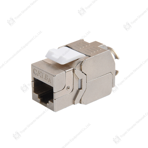
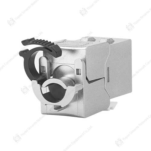
- Keystone jack cat6 modules, used for standard gigabit copper connections at the work area outlet.
- RJ45 keystone jack ports compatible with most blank patch panel and faceplate housings.
- Net Keystone Jack style modules, designed for either tool-free or punch down termination depending on the installer's preference.
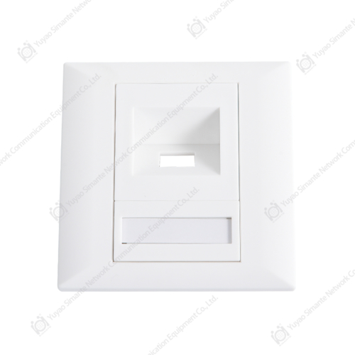
- Network face plate and faceplate housings, available in single port, dual port, and multi port layouts to match a Patch Panel 24 Port or larger backbone configuration.
Faceplate manufacturers generally offer both flush mount and surface mount faceplate options, so the same keystone jack can be installed in drywall, in a raised floor box, or on the surface of a wall, depending on the building type. Because a faceplate is simply a housing for one or more keystone jacks, the actual electrical performance of the connection still depends on matching the faceplate's keystone jacks to the same cable category used by the patch panel and cabling behind it.
Matching Patch Panel Ports With RJ45 Connectors and Patch Cords
On the front of the patch panel, each port accepts a standard RJ45 plug. The patch cords used to make these connections, sometimes referred to in shorthand as Patch Panel patches, are short factory or field-terminated cables fitted with an RJ45 male connector on each end. RJ45 connector manufacturers typically produce these connectors to match Cat5e, Cat6, or Cat6A specifications, and selecting a connector rated for the same category as the patch panel and keystone jacks helps avoid an unintended bottleneck in the link. It is worth noting that the term patch panel also appears in unrelated contexts, such as patch panel for car audio systems, which refers to amplifier wiring distribution panels in vehicles; that usage is unrelated to the network structured cabling patch panels described throughout this guide. Working with established Patch Panel manufacturers that also produce matching keystone jacks, faceplates, and RJ45 connectors can simplify sourcing, since the cable category, color coding, and termination style are more likely to be consistent across the entire structured cabling system.
Isometric View: Anatomy of a Rack-Mounted Patch Panel
The isometric diagram above is a simplified schematic illustration of a rack-mounted patch panel, intended to show the general layout of its main components rather than an exact technical drawing of any specific model. The front face of the panel contains a row of keystone jack ports, which is where individual network cables are terminated using RJ45 keystone jack connectors. A mounting bracket along the side of the panel allows it to be secured into a standard 19 inch equipment rack, keeping the panel aligned with other rack-mounted equipment such as a network switch. On the rear side of the panel, IDC punch down terminals, commonly following a 110 or Krone style termination method, are used to connect the incoming horizontal cabling to each keystone jack port. A label or ID strip near the front ports is typically included so that each port can be numbered, which helps with cable management and troubleshooting once the patch panel is installed in a live structured cabling system.
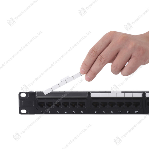
The photograph below shows a representative range of patch panel and faceplate components.
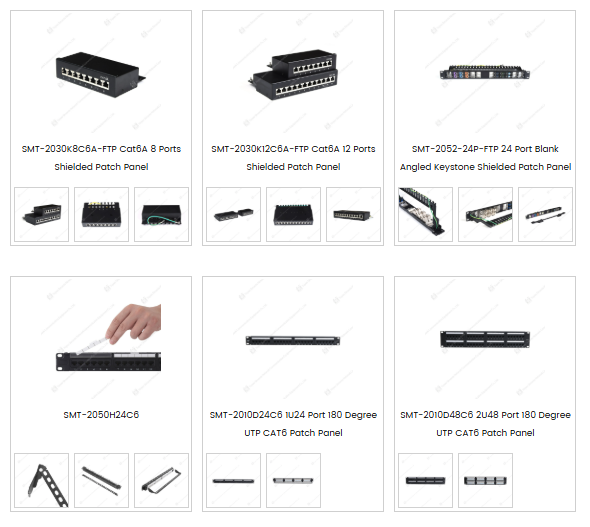
The photograph above shows a range of patch panel and faceplate components, including shielded Cat6A patch panels in 8 port and 12 port configurations, a 24 port blank angled keystone shielded patch panel, and UTP Cat6 patch panels in 24 port and 48 port 180 degree configurations. Blank patch panel models accept individual keystone jacks of the installer's choice, which allows a single patch panel chassis to support different jack types, such as Cat6 keystone jacks or fiber adapters, within the same rack space. Patch panel box style products, shown alongside the rack-mounted units, are typically used for smaller installations where only a handful of network drops need to be organized outside of a full equipment rack. Across all of these patch panel formats, RJ45 keystone jack ports remain the common termination point for standard copper structured cabling, while the rear of each unit generally accepts an IDC punch down termination for the incoming cable runs. Selecting between 8 port, 12 port, 24 port, and 48 port patch panel options generally comes down to the number of cable drops being terminated in a given rack or wiring closet.
About Yuyao Simante Network Communication Equipment Co., Ltd.
Yuyao Simante Network Communication Equipment Co., Ltd. is a manufacturer focused on structured cabling system components and optical fiber products, covering design, development, sales, and service. Operating for nearly 20 years, the company maintains production lines for keystone jacks, patch panels, faceplates, and other structured cable products used in structured cabling, network communication, and smart home applications. The manufacturing setup includes regular and customization production lines, along with fully automatic and semi-automatic injection molding equipment, supporting a stable annual output in the range of several million units.
A research and development team of more than 10 engineers and over 30 full-time technical staff works on quality control and product updates, supporting the consistency of patch panel, keystone jack, and faceplate manufacturing from the design stage onward. As a supplier among structured cabling system manufacturers, Simante serves customers across regions including Europe, Australia, Africa, the Middle East, and Southeast Asia, and also takes part in OEM and ODM cooperation involving patch panel, keystone jack, and faceplate components, in addition to custom 12, 24, and 48 port keystone network patch panels in 90 degree and 180 degree designs across CAT5E, CAT6, and CAT6A categories.
Frequently Asked Questions About Patch Panels and Switches
Q1. What is the main difference between a patch panel and a switch?
A patch panel is a passive device that organizes and terminates structured cabling, while a switch is an active networking device that processes and directs data traffic between connected ports.
Q2. Do I need both a patch panel and a switch in a network setup?
In most structured cabling systems, yes. The patch panel terminates the horizontal cabling runs, and short patch cords then connect specific patch panel ports to a switch, separating cable management from active networking equipment.
Q3. What port counts are commonly available for patch panels?
Patch panels commonly come in 8, 12, 24, and 48 port configurations, with Patch Panel 24 Port and 48 port models widely used in office and telecom room environments.
Q4. Can a patch panel be used without a switch?
A patch panel alone does not provide network connectivity, since it only organizes cabling. A switch, router, or other active equipment is still needed on one side of the patch panel to enable data transmission.
Q5. What is the difference between RJ45 keystone jacks and RJ45 male connectors used with a patch panel?
Keystone jacks are the female RJ45 ports mounted in patch panels and faceplates for cable termination, while an RJ45 male connector is the plug end on a patch cord that inserts into those keystone jack ports or into a switch port.