Español
 عربى
عربى русский
Content
- 1 Core Components of a Structured Cabling System
- 2 Fiber Optic Patch Panel Design, Port Configurations and Rack Mount Options
- 3 Bandwidth Performance of Copper Cabling Categories Used with Keystone Jacks and Patch Panels
- 4 Connector Types for Fiber Optic Patch Panels: SC, LC, FC and ST
- 5 Scalable Port Density in Rack Mount Fiber Optic Patch Panel Design
- 6 Industry Trends Shaping Structured Cabling and Fiber Distribution Deployment
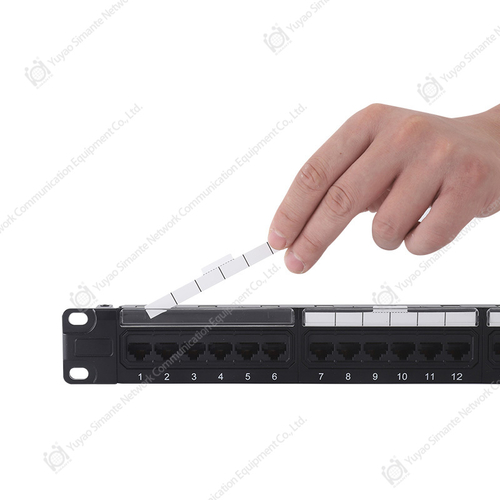
- 7 Installation Practices for Patch Panels, Faceplates and Keystone Jacks
- 8 Compatibility Considerations for Fiber and Copper Cabling Components
- 9 About Yuyao Simante Network Communication Equipment Co., Ltd
- 10 Frequently Asked Questions
A structured cabling system is a standardized network infrastructure that uses patch panels, keystone jacks, faceplates and connectors to organize voice, data and fiber optic connections inside a building or data center. Rather than running individual cables directly to end devices, a structured cabling system routes cabling to centralized distribution points, such as a patch panel or fiber distribution panel, where connections can be tested, rearranged or expanded without disturbing the rest of the network. This approach is defined by widely referenced standards, including ANSI/TIA-568 and ISO/IEC 11801, which specify performance requirements for copper categories such as Cat5e, Cat6 and Cat6a, as well as testing criteria referenced for fiber optic connectors. A well planned structured cabling system typically combines a network cabling solution built from copper patch panels, RJ45 keystone jacks, network faceplates and fiber optic patch panels, all working together to support Ethernet, voice and video traffic. Because these components generally follow common mechanical standards, structured cable products from different production runs can usually be mixed within the same rack or wall enclosure, which simplifies long term maintenance and future upgrades.
Fiber optic patch panels play a central role in this framework whenever a network needs to extend beyond the length limits of copper cabling or requires additional bandwidth for backbone and data center links. A fiber optic patch panel, sometimes called an ODF patch panel or fiber distribution panel, is the point where incoming fiber optic cables are spliced or connected to patch cords that continue on to switches, servers or other network equipment. The sections below look at how structured cabling components are selected, how a fiber optic patch panel is typically configured, and what installation practices help keep both the copper and fiber optic segments of a network cabling solution running reliably over time.
Core Components of a Structured Cabling System
A structured cabling system is generally organized into a small number of component categories, each manufactured to meet defined mechanical and electrical requirements. The table below summarizes the primary structured cabling system components referenced throughout this article, including patch panel types, keystone jacks, faceplates and connector hardware. Understanding the role of each structured cabling products component helps installers select compatible parts and helps facility managers plan capacity for future growth. In most commercial installations, these components are combined inside a wall mount or rack mount enclosure, with cabling routed through dedicated management trays to reduce strain on connectors.
| Component | Typical Function | Common Variants |
|---|---|---|
| Patch Panel | Provides a fixed termination point for horizontal cabling and allows quick reconfiguration using patch cords | Blank patch panel, patch panel cat6, fiber optic patch panel, ODF panel |
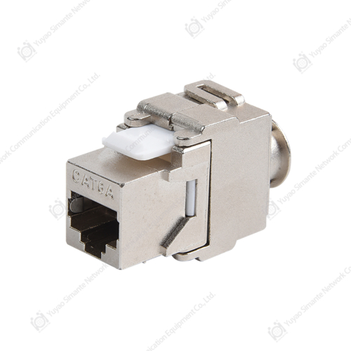
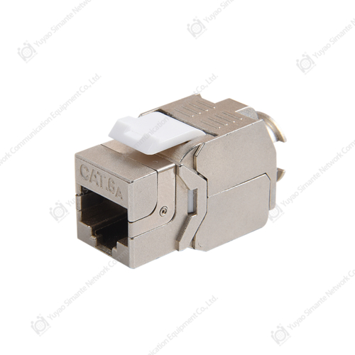
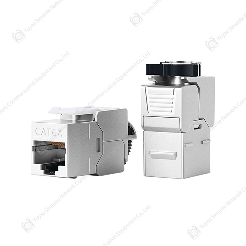
| Keystone Jack | Terminates an individual cable run at the patch panel or faceplate end and snaps into a standard keystone opening | Keystone jack cat6, rj45 keystone jack, shielded and unshielded versions |
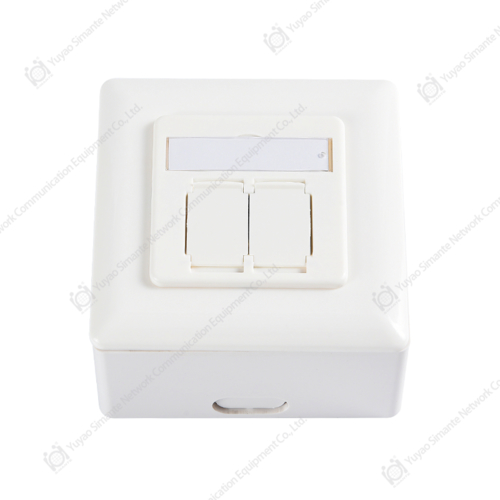
| Faceplate | Houses one or more keystone jacks at the wall outlet or work area end of the cabling run | Single port, dual port and multi port network face plate |
| RJ45 Connector | Terminates twisted pair copper cable for connection into a keystone jack, patch panel port or network device | RJ45 male connector, shielded RJ45 connector |
| Fiber Optic Patch Panel / ODF | Organizes and protects fiber splices or connectors, providing an interface between outside plant fiber and patch cords | 12 to 96 core panels, SC, LC, FC and ST adapter types |
Fiber Optic Patch Panel Design, Port Configurations and Rack Mount Options
A fiber optic patch panel and an optical distribution frame, often shortened to ODF panel, describe closely related equipment used to organize fiber connections, although the terms are sometimes used slightly differently across regions and suppliers. In general usage, a fiber patch panel refers to a compact rack mount or wall mount enclosure that holds a limited number of ports, typically used inside a telecom room, floor distribution closet or small data center. An ODF panel usually describes a larger frame, often with multiple removable trays, used at a central office, headend or larger data center to manage higher fiber counts. Both a fiber ODF and a standard fiber panel perform the same underlying function, which is to protect fusion splices or connectorized fiber, distribute incoming and outgoing fiber cores, and provide a stable, labeled point for testing and patching. Because terminology varies, buyers evaluating a fiber distribution panel are generally advised to confirm port count, tray configuration and connector type rather than relying on the product name alone.
Fiber optic patch panels are commonly manufactured in 12, 24, 48 and 96 core configurations, with some high density fiber optic patch panel designs supporting even higher counts for data center applications. Port count is usually matched to the rack unit height of the enclosure, since each 1U of rack space can typically accommodate a defined number of adapter positions depending on adapter type and tray design. A 24 port fiber optic patch panel is a common choice for smaller telecom rooms and FTTH distribution points, while higher port counts are more often selected for data center and central office backbone applications. Rack mount fiber optic patch panel designs are intended for installation in a standard 19 inch equipment rack, while wall mount versions are used in smaller spaces such as floor distribution boxes or FTTH access points where a full rack is not practical.
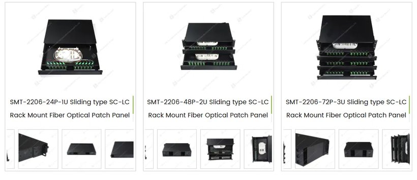
The photograph above shows a rack mount fiber optic patch panel series manufactured by Yuyao Simante Network Communication Equipment Co., Ltd, illustrating how port count scales with enclosure height. The 1U version accommodates 24 ports, the 2U version accommodates 48 ports, and the 3U version accommodates 72 ports, following a sliding drawer design that allows the front tray to extend outward for splicing, patching and maintenance without removing the panel from the rack. Each unit uses SC or LC adapters mounted on the front panel, with splice trays and fiber management features housed inside the drawer to help protect fiber bend radius and reduce the risk of fiber damage during service. This type of sliding type SC LC fiber patch panel ODF is intended to simplify moves, adds and changes in environments where technicians need repeated physical access to splices and connectors. Rack mount fiber optic patch panel products of this kind are typically installed in telecom rooms, data centers, ISP central offices and FTTH distribution points where organized, serviceable fiber termination is needed.
Bandwidth Performance of Copper Cabling Categories Used with Keystone Jacks and Patch Panels
Copper structured cabling performance is defined by category ratings established under ANSI/TIA-568 and ISO/IEC 11801, which specify a minimum frequency bandwidth for each cable and connecting hardware category. According to these standards, Category 5e cabling is rated for 100 MHz, Category 6 cabling is rated for 250 MHz, Category 6a cabling is rated for 500 MHz, and Category 8 cabling is rated for 2000 MHz. Because a patch panel, a Cat6 keystone jack and an RJ45 keystone jack are all part of the same channel, every component in the link, from the patch panel cat6 port to the keystone jack cat6 termination to the RJ45 male connector at the equipment end, needs to meet or exceed the category rating for the link to perform as intended. The chart below illustrates how bandwidth capacity increases across these categories, which helps explain why many enterprise network cabling solution designs have shifted toward Category 6 and Category 6a hardware for new installations. Selecting patch panel and keystone jack hardware rated for the same or higher category than the installed cable is a widely followed practice among structured cabling products manufacturers and installers, since mismatched components can limit the achievable bandwidth of the entire link.
The chart above compares the minimum bandwidth rating of four common copper cabling categories as defined by ANSI/TIA-568 and related ISO/IEC 11801 documentation. Category 5e, still found in many older office installations, supports a 100 MHz bandwidth and is generally associated with Gigabit Ethernet at standard cable lengths. Category 6 doubles that figure to 250 MHz and can support 10 Gigabit Ethernet over shorter channel lengths, which is one reason Cat6 keystone jack and patch panel cat6 hardware remain widely specified in new network cabling solution projects. Category 6a extends bandwidth to 500 MHz and adds tighter control of alien crosstalk, allowing 10 Gigabit Ethernet to run over the full 100 meter channel length permitted by the standard. Category 8, rated at 2000 MHz, is intended mainly for very short data center connections rather than general office cabling. Because bandwidth requirements tend to increase as networks are upgraded, many facility managers look for patch panel and keystone jack manufacturers whose product lines offer a clear upgrade path from Cat6 to Cat6a hardware within the same footprint.
Connector Types for Fiber Optic Patch Panels: SC, LC, FC and ST
Fiber optic patch panels are built around a small number of standardized connector and adapter types, most commonly SC, LC, FC and ST. SC connectors use a push pull latching mechanism and a relatively large 2.5 millimeter ferrule, and remain common in telecom and enterprise fiber distribution panel applications. LC connectors use a smaller 1.25 millimeter ferrule with a similar latch style, which allows roughly twice the port density of SC connectors within the same panel width, making LC a frequent choice for high density fiber optic patch panel data center designs. FC connectors use a threaded coupling that provides a secure mechanical connection and are still specified in some outside plant and test environments where vibration resistance is a priority. ST connectors use a spring loaded twist lock mechanism and were historically common in early multimode fiber optic patch panel deployments, though newer projects more often specify SC or LC hardware.
Optical performance for these connector types is commonly evaluated against criteria referenced in Telcordia GR-326-CORE and IEC 61753-1, which describe test methods for insertion loss, return loss and mechanical durability of single mode fiber optic connectors. Published industry benchmarks referenced across multiple connector manufacturers commonly describe typical maximum insertion loss in the range of approximately 0.2 to 0.3 dB for factory terminated SC, LC and FC connectors under normal mating conditions. Return loss performance is often benchmarked at 50 dB or higher for UPC polished connectors and 60 dB or higher for APC polished connectors, based on the same category of published sources. Mechanical durability is frequently benchmarked at a minimum of 500 mating cycles under Telcordia GR-326-CORE style durability testing. These figures represent commonly referenced industry benchmarks rather than guaranteed values for any specific product, since actual performance can vary by manufacturer, ferrule quality and field handling.
The chart above presents commonly referenced maximum insertion loss benchmarks in decibels for SC, LC, FC and ST connector types, based on published industry test criteria such as Telcordia GR-326-CORE. SC, LC and FC connectors are frequently associated with maximum insertion loss benchmarks near 0.3 dB when properly terminated and mated under normal conditions. ST connectors, which rely on a twist lock coupling rather than a push pull or threaded interface, are more often associated with a slightly higher typical benchmark near 0.5 dB due to differences in alignment tolerance. Lower insertion loss generally means less optical signal is lost at each connection point, which becomes more significant in fiber ODF and fiber distribution panel applications that include multiple splice and patch points along a single link. These figures are general industry benchmarks rather than specifications guaranteed for a particular batch of connectors, and actual results depend on ferrule polish quality, cleaning practices and mating cycle count. Network designers planning a fiber patch panel for a long backbone run, or a high density fiber optic patch panel data center layout, often factor cumulative insertion loss across all connection points into their overall link budget calculations.
Scalable Port Density in Rack Mount Fiber Optic Patch Panel Design
Rack mount fiber optic patch panel enclosures are typically sized in standard rack units, commonly abbreviated 1U, 2U or 3U, with port count scaling according to how many adapter positions and splice trays fit inside each unit of vertical rack space. The sliding tray fiber optic patch panel series referenced earlier in this article follows this pattern, offering a 24 port configuration in a 1U enclosure, a 48 port configuration in a 2U enclosure and a 72 port configuration in a 3U enclosure. This kind of scaling allows a facility to plan cabling capacity in advance, selecting a 24 port rack mount fiber optic patch panel for a smaller telecom room or a higher port count panel for a data center backbone without changing the overall panel design or adapter type. Because each additional rack unit adds a proportional number of ports in this design, planners can estimate future capacity needs by rack space budget rather than evaluating an entirely different fiber panel product line for each project size.
The chart above shows how port count scales with rack unit height for a representative sliding tray fiber optic patch panel series, based on the 1U, 2U and 3U configurations referenced in this article. The 1U enclosure accommodates 24 ports, the 2U enclosure accommodates 48 ports, and the 3U enclosure accommodates 72 ports, reflecting a proportional increase of 24 ports for every additional rack unit of height in this particular sliding drawer design. This kind of predictable scaling is useful when comparing a fiber patch panel option against alternative panel styles that may pack ports less efficiently or that lack a sliding tray for splice access. Facilities with limited rack space often favor higher port density per rack unit, since it reduces the number of enclosures needed to terminate a given fiber count. At the same time, very high port density panels require careful internal fiber management to help preserve minimum bend radius, so port count is only one factor to weigh alongside splice tray design and cable routing features when selecting a fiber distribution panel.
Industry Trends Shaping Structured Cabling and Fiber Distribution Deployment
Demand for structured cabling system components, including patch panels, keystone jacks and fiber optic patch panels, has been shaped in recent years by the continued expansion of data centers, cloud infrastructure and fiber to the home deployments. According to one industry market research report, the global structured cabling market was estimated to exceed 20 billion United States dollars in 2025, with a projected compound annual growth rate near 8 percent through the mid 2030s, attributed largely to data center and cloud infrastructure expansion. The same category of market analysis has noted that local area network applications have historically accounted for a majority of installed structured cabling volume by revenue, while data center applications represent one of the faster growing segments as organizations continue to expand server and storage capacity. Fiber to the home programs have also contributed to demand for FTTH fiber distribution panel solutions, since each new subscriber connection typically requires a dedicated splice or patch point at a distribution panel between the outside plant fiber and the customer premises. These trends suggest that both copper focused structured cable products, such as Cat6 keystone jack and patch panel hardware, and fiber optic patch panel products are likely to remain relevant as networks continue to expand across copper and fiber segments in parallel.
The chart above illustrates an approximate distribution of structured cabling deployment by application category, based on published market research estimates rather than a single verified global census. Local area network deployments, covering typical office and enterprise environments, have historically represented the largest single share of structured cabling volume, consistent with the broad presence of patch panels, keystone jacks and faceplates across ordinary commercial buildings. Data center applications represent a smaller but generally faster growing share, reflecting the shift toward higher density server rooms and cloud infrastructure that often rely more heavily on fiber optic patch panel and high density fiber distribution panel products. The remaining share includes other applications such as industrial, residential and specialized telecom environments, which vary considerably by region and project type. Because market estimates differ between research providers, the percentages shown here should be read as a general illustration of relative scale rather than a precise figure for any specific year or region. This general pattern is one reason many structured cabling products manufacturers maintain parallel product lines covering both copper patch panel and keystone jack hardware alongside fiber optic patch panel and ODF panel products.
Installation Practices for Patch Panels, Faceplates and Keystone Jacks
Installing structured cabling system components generally follows a similar sequence whether the project involves a copper patch panel, a network faceplate or a fiber optic patch panel, although the specific termination method differs between copper and fiber media. The steps below describe a general installation sequence that is commonly followed in commercial cabling projects, though local codes, cable manufacturer instructions and project specifications should always take priority over any general description.
- Plan cable routes and label both ends of every cable run before installation begins, so that the connection at the patch panel cat6 port or fiber panel adapter matches the corresponding network face plate or wall outlet.
- Mount the patch panel, blank patch panel filler plates and cable management hardware inside the rack or wall enclosure, leaving adequate space for cable bend radius on the rear side of the panel.
- Terminate each copper cable into a Cat6 keystone jack or RJ45 keystone jack using the termination tool specified by the jack manufacturer, then snap the completed keystone jack into the patch panel or network faceplate opening.
- For a fiber optic patch panel, route incoming fiber into the splice tray or adapter position, complete fusion splicing or connectorization, and dress excess fiber length inside the tray to help maintain the minimum bend radius specified for the cable type.
- Test every completed link with an appropriate cable certification tester or optical loss test set before placing the connection into service, and record results for future reference.
- Label the front of the patch panel, faceplate and fiber panel ports clearly, matching the documentation created during the planning stage.
Compatibility Considerations for Fiber and Copper Cabling Components
Because structured cabling system components are produced by many different manufacturers, compatibility is generally maintained through adherence to common mechanical and electrical standards rather than through a single proprietary design. Keystone jacks, whether described as a Cat6 keystone jack or a general rj45 keystone jack, are built to a standardized keystone footprint, so jacks from different structured cable products component lines can generally be inserted into the same patch panel or network faceplate opening. In fiber applications, compatibility is centered on adapter and connector type rather than a keystone footprint, so a fiber optic patch panel populated with SC adapters is generally compatible with SC terminated patch cords and pigtails, while an LC populated panel requires LC terminated cords, regardless of which fiber panel manufacturer produced the enclosure. Buyers evaluating a fiber optic patch panel supplier, an ODF patch panel manufacturer or a rack mount fiber patch panel factory for a new project are generally advised to confirm adapter type, port count and rack unit height against their existing cabling plant before placing an order, since mismatched connector types cannot be mated without an adapter conversion. Confirming these details in advance helps avoid rework and supports a smoother transition when expanding an existing network cabling solution with additional patch panel, keystone jack or fiber optic patch panel capacity.
About Yuyao Simante Network Communication Equipment Co., Ltd
Yuyao Simante Network Communication Equipment Co., Ltd is a professional manufacturer of network cabling solutions and optical fiber products, integrating design, development, sales and service. In nearly 20 years of service, the company has focused on meeting customer needs through applied engineering expertise, aiming to provide value to customers from the earliest stages of project communication. Based on a mature research and development system, product quality stability is addressed starting at the design stage. The company maintains a technical team of more than 10 engineers and over 30 full time technical staff who continue to contribute professional input toward quality improvement and product updates, including the fiber optic patch panel, keystone jack, patch panel and faceplate product lines referenced throughout this article.
Frequently Asked Questions
| Question | Answer |
|---|---|
| Q1. What is the difference between a fiber optic patch panel and an ODF panel | The terms describe similar equipment, though a fiber optic patch panel usually refers to a smaller panel used in a telecom room or FTTH distribution point, while an ODF panel typically describes a larger frame with multiple trays used at a central office or larger data center. Both perform the same core function of organizing and protecting fiber connections. |
| Q2. How do I choose between SC and LC connectors for a fiber patch panel | The choice generally depends on required port density and compatibility with existing patch cords. LC connectors allow more ports within the same panel width due to their smaller ferrule size, while SC connectors remain common where existing infrastructure already uses SC terminated cords. |
| Q3. Should I select a rack mount or wall mount fiber distribution panel | Rack mount panels are generally suited to installations with an existing 19 inch equipment rack, such as data centers and telecom rooms, while wall mount panels are more often used in smaller spaces such as FTTH access points or floor distribution boxes where a full rack is not available. |
| Q4. Can Cat6 keystone jacks be used with a Cat6a patch panel | Cat6 keystone jacks can generally be physically inserted into a Cat6a rated patch panel opening, but the overall link will typically only achieve Cat6 level bandwidth performance, since channel performance is limited by the lowest rated component in the path. |