Español
 عربى
عربى русский
Content
- 1 The Six Subsystems of a Structured Cabling System
- 2 Key Components: Patch Panels, Keystone Jacks, and Faceplates Explained
- 3 CAT6 vs CAT6A vs CAT7: Which Cable Standard Fits Your Application?
- 4 Data Center Structured Cabling: Design Principles for Server Room Environments
- 5 How to Install a Patch Panel: Step-by-Step Best Practice
- 6 About Yuyao Simante Network Communication Equipment Co., Ltd.
- 7 Frequently Asked Questions
Structured cabling is a standardised, hierarchical wiring infrastructure designed to support multiple hardware uses simultaneously — voice, data, video, and building automation — through a unified system of cables, connectors, and management hardware. Traditional cabling, by contrast, is application-specific: a separate dedicated cable run is installed for each individual device or service, with no common architecture or upgrade path. The practical difference is profound: a structured cabling system supports technology changes, capacity expansions, and troubleshooting without rewiring; a traditional installation typically requires partial or full replacement every time the underlying technology changes. For any commercial, industrial, or data center environment where network performance and longevity matter, understanding this difference is the foundation of sound infrastructure planning.
Infrastructure Lifespan and Flexibility: Structured vs Traditional Cabling
This chart contrasts structured and traditional cabling across five infrastructure performance dimensions. A structured cabling system achieves an expected lifespan of 15–25 years — more than double the 5–8 year cycle of application-specific traditional wiring — because its passive physical layer remains valid across multiple technology generations. The multi-application support (6+ simultaneous services) versus single-application traditional wiring explains why structured cabling is the standard in every category of commercial, enterprise, and data center deployment today. The upgrade-without-rewiring figure of up to 85% reflects the ability to reuse existing cable runs when upgrading active equipment, a financial and operational advantage that compounds significantly over a building's service life.
The Six Subsystems of a Structured Cabling System
A complete structured cabling system is not a single product — it is an architecture of six interrelated subsystems, each with a defined role and standardised specification. Understanding these subsystems is essential for any procurement, design, or installation decision involving structured cabling components.
- Entrance Facility (EF): the point where external service provider cables enter the building and connect to the internal distribution network. Includes primary protection hardware and service demarcation equipment.
- Equipment Room (ER): centralised space housing major telecommunications equipment, servers, and cross-connect hardware. The equipment room is the termination point for backbone cabling and requires careful thermal and power management.
- Backbone Cabling: high-capacity cable runs between the equipment room and telecommunications rooms on each floor — typically multi-pair copper or multi-strand fibre. Backbone cables carry aggregated traffic and must be sized for peak load projections, not current demand.
- Telecommunications Room (TR): floor-level distribution point where backbone cabling terminates and horizontal cabling originates. Houses patch panel arrays, switches, and intermediate distribution frames.
- Horizontal Cabling: runs from the telecommunications room to individual work area outlets. The dominant component in a cat6 structured cabling system or CAT6A installation — length is standardised at a maximum of 90 m for permanent links under TIA-568 and ISO 11801.
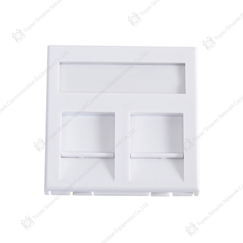
- Work Area Components: the user-facing elements — network face plates, keystone jacks, and patch cords — connecting end devices to the horizontal cabling run. These are the most frequently disturbed components in the system and must be selected for both performance and mechanical durability.
| Subsystem | Primary Component | Key Standard | Upgrade Frequency |
|---|---|---|---|
| Backbone | Fibre / Cat6A trunk cable | TIA-568 / ISO 11801 | 10–20 years |
| TR / Distribution | Patch panel cat6, cable tray | TIA-568C.2 | 10–15 years |
| Horizontal | Cat6 / Cat6A UTP/STP | Max 90 m permanent link | 8–15 years |
| Work Area | Keystone jack cat6, faceplate, patch cord | 750 mating cycles min. | 5–10 years |
Key Components: Patch Panels, Keystone Jacks, and Faceplates Explained
The performance and longevity of a network cabling solution depends heavily on the quality of its passive components. Three components in particular determine the day-to-day reliability of the system at the distribution and work-area level.
Patch Panels: The Cross-Connect Hub
A patch panel is a mounted array of ports — typically 24 or 48 — that terminates incoming horizontal cable runs on the rear (punch-down or toolless) and presents standardised RJ45 jacks on the front for patch cord connection to active equipment. The patch panel cat6 standard specifies return loss, insertion loss, NEXT (near-end crosstalk), and ANEXT (alien NEXT) performance parameters that must be met at the component level for the channel to pass certification. A high density patch panel — typically 48 ports in 1U — is the standard choice for data center server room cabling solutions where rack space is a limiting constraint. A blank patch panel is used to fill unused rack units, maintaining airflow management and cable organisation in structured rack environments.
When evaluating a patch panel manufacturers offering, key quality indicators include port body material (high-impact ABS or polycarbonate vs thin styrene), PCB board thickness and via quality (critical for consistent NEXT performance across the port array), rear IDC contact plating (50 µin gold minimum at the mating interface), and cable management bar quality. A patch panel that passes component-level testing but uses thin PCB material will develop intermittent contact issues within 3–5 years in high-activity environments.
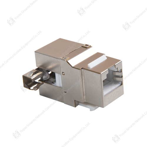
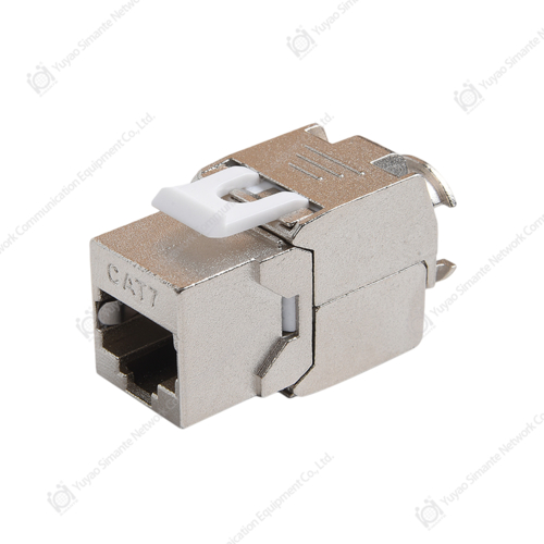
Keystone Jacks: The Work Area Termination Standard
The keystone jack is the universal modular termination format used across faceplates, surface boxes, patch panels, and keystone-compatible enclosures. A keystone jack cat6 terminates one horizontal cable run and presents a single RJ45 female port to the user. Its 110-type IDC (Insulation Displacement Contact) rear termination accepts both T568A and T568B wiring patterns — the pattern must be consistent throughout the installation. Net keystone jack designs from quality keystone jack manufacturers incorporate internal isolation between wire pairs to maintain NEXT performance at the termination point, where crosstalk risk is highest due to the untwisting required for termination.
The rj45 keystone jack format's key advantage is interchangeability: a single faceplate format supports voice, data, and specialised applications by populating with the appropriate jack module, eliminating the need for application-specific outlet designs. For any office network cabling or commercial cabling solutions project, specifying keystone-format outlets at design stage is the correct approach regardless of whether all ports are populated at initial installation.
Faceplates: Work Area Outlet Housing
The faceplate — or network face plate — houses the keystone jacks at the work area outlet and provides the mechanical interface between the wall box or surface mount enclosure and the user. Standard formats include 1-port, 2-port, 4-port, and 6-port configurations in single-gang (UK/EU 86×86 mm) and US-standard (single-gang electrical box) sizes. Faceplate manufacturers producing for structured cabling applications supply both loaded (pre-populated with jacks) and unloaded (blank) configurations. A faceplate rj45 port loading should include dust shutters on unused ports to prevent contamination of the IDC contacts, which causes intermittent connectivity failures that are difficult to diagnose without specialised test equipment.
Channel Failure Contribution by Component Type (% of certified failures)
This chart shows the distribution of channel certification failure causes in installed structured cabling systems, based on field testing data across commercial and data center deployments. Keystone jack terminations account for 38% of failures — the largest single category — primarily due to inconsistent pair untwisting length during punch-down, incorrect seating depth, and IDC contact contamination at the work area outlet. Patch panel port termination follows at 27%, reinforcing that the highest-risk phase of any structured network cabling project is the termination work, not the cable run itself. These findings explain why specifying quality keystone jack manufacturers and patch panel manufacturers with verified IDC geometry and contact plating standards has a greater impact on first-test certification pass rates than cable grade selection alone.
CAT6 vs CAT6A vs CAT7: Which Cable Standard Fits Your Application?
The cat6 vs cat6a decision is the most common cable specification choice in current commercial structured cabling solutions and data center projects. CAT7 is a third option with specific use cases. The right choice depends on application bandwidth, channel length, and the balance between current requirements and future-proofing investment.
| Attribute | Cat6 (U/UTP) | Cat6A (U/FTP) | Cat7 (S/FTP) |
|---|---|---|---|
| Max bandwidth | 250 MHz | 500 MHz | 600 MHz |
| Max data rate (100m) | 1 Gbps | 10 Gbps | 10 Gbps |
| Shielding | Unshielded (UTP) | Individual pair foil | Per-pair foil + braid |
| Cable diameter | ~6 mm | ~7.5 mm | ~8 mm |
| Best for | Office LAN, SME | Data center, 10GbE floor | High-interference industrial |
| Connector compatibility | Standard RJ45 | Standard RJ45 | GG45 / TERA (non-standard) |
For most office network cabling and intelligent building cabling projects, Cat6A is the recommended specification for new builds: it supports 10 Gbps at full 100 m channel length, uses standard RJ45 male connector and keystone interfaces, and provides margin for future PoE++ (90W) power delivery applications without thermal performance degradation. The shielded vs unshielded cable choice within Cat6A is determined by the electromagnetic environment — F/UTP (foiled unshielded twisted pair) is sufficient for most commercial environments; S/FTP is specified for industrial or high-RF-interference sites.
Data Center Structured Cabling: Design Principles for Server Room Environments
Data center structured cabling operates at a different density and performance demand level than enterprise office cabling. A modern hyperscale or enterprise data center may house 10,000–100,000 individual cable connections within a single hall, with server room cabling solutions required to support hot-swap port changes, real-time moves/adds/changes (MAC), and zero-downtime fault isolation. The cabling architecture choices made at design stage directly determine the operational cost of running the facility for its 10–20 year service life.
Key design principles for data center cabling solutions include:
- Top-of-rack (ToR) vs end-of-row (EoR) switching: ToR architectures minimise horizontal cable runs to 3–10 m per server, dramatically reducing cable volume and improving airflow. EoR architectures consolidate switching but require longer, more complex horizontal runs to each rack.
- High density patch panel deployment: 48-port high density patch panels in 1U reduce the rack units consumed by copper cross-connect, freeing space for active equipment. Angled patch panels further reduce patch cord bend radius stress and improve port accessibility in dense environments.
- Structured cable management: horizontal and vertical cable managers with defined fill ratios (maximum 50% fill in cable trays to permit airflow and future adds) are mandatory in any data center structured cabling design. Unlabelled or over-filled cable paths are the leading cause of unplanned downtime during maintenance operations.
- Pre-terminated trunk assemblies: factory-terminated multi-pair trunks connect distribution frames to ToR switch panels, eliminating field termination error in the highest-density zones of the installation.
Annual Network Downtime Hours vs Cabling Infrastructure Quality Level
This line chart tracks annual network downtime hours across a six-year operational period for three infrastructure quality levels: certified quality structured cabling products, standard structured cabling, and traditional or ad-hoc wiring. The certified quality structured cabling installation maintains near-flat downtime at 2–3.5 hours per year across the full period — the small upward trend reflects normal ageing of patch cords and work area components that are replaced on schedule. Standard structured cabling shows a gradual increase from 4 to 12 hours annually as termination quality issues and undocumented changes accumulate. The traditional wiring profile grows steeply from 8 hours in year one to 38 hours by year six — a trajectory driven by the compounding effect of undocumented, non-standardised changes that make fault isolation increasingly time-consuming. This data underlines why investing in certified structured cabling components from qualified structured cabling accessories manufacturers and structured cabling suppliers is not a cost item — it is a downtime reduction strategy with directly measurable return.
How to Install a Patch Panel: Step-by-Step Best Practice
Knowing how to install a patch panel correctly prevents the most common cause of channel certification failures — poor termination practice. The following sequence applies to a standard 24-port or 48-port patch panel cat6 rear punch-down installation:
- Label and route incoming cables before termination. Each cable should be identified at the patch panel end, and the routing path documented in the as-built record. Cable labels applied now will save hours of troubleshooting over the system's service life.
- Strip the cable jacket to the minimum length required — typically 20–25 mm. Exposing more jacket than necessary increases the untwisted pair length near the termination point, directly degrading NEXT performance at the port.
- Maintain pair twist to within 13 mm of the IDC contact. This is the single most important termination practice for Cat6 and Cat6A performance. Any additional untwisted length creates a wire segment acting as an antenna for crosstalk coupling.
- Seat pairs fully into the IDC slot before using the punch-down tool. Partially seated conductors result in inconsistent contact resistance that passes visual inspection but fails electrical testing under channel certification.
- Use a calibrated punch-down tool set to the correct cut-and-terminate position (not the no-cut position). Confirm the conductor is seated flush with the IDC housing surface after each punch.
- Dress and secure cables in the rear cable management trough, maintaining a minimum 25 mm bend radius for Cat6A. Over-tightened cable ties are one of the most common causes of post-installation performance degradation.
- Test every port with a channel certifier before making the panel live. Record the test results as part of the as-built documentation — certification records are the primary reference for future troubleshooting and demonstrate compliance with the installation warranty requirements of component manufacturers.
Component Quality Radar: Certified vs Economy Structured Cabling Products
This radar chart compares certified quality structured cabling products against economy-grade alternatives across five performance dimensions: NEXT performance, contact life cycles, mechanical fit precision, insertion loss, and long-term durability. The certified products maintain near-maximum scores across all five axes — in particular contact life (rated to 750+ mating cycles per TIA-568 minimum, often tested to 1,500+ cycles by quality manufacturers) and NEXT performance (meeting or exceeding channel margin requirements at the highest test frequency). Economy products score moderately on simpler parameters like insertion loss but fall noticeably on NEXT performance and mechanical fit — the two parameters that most directly affect channel certification pass rates and long-term connection reliability under real-world use. For any OEM network cabling products procurement or structured cabling supplier selection, this performance gap is the reason component specification should be verified against certified test data rather than assumed from product claims.
About Yuyao Simante Network Communication Equipment Co., Ltd.
Yuyao Simante Network Communication Equipment Co., Ltd. is a professional manufacturer of network cabling solutions and optical fiber products, integrating design, development, sales, and service. With nearly 20 years of industry experience, Simante is committed to meeting customer needs through deep technical expertise and delivering genuine value from the very first point of contact.
Backed by a mature research and development system, Simante's quality stability is built in at the design stage — not added as an afterthought. The company maintains a team of more than 10 engineers and over 30 full-time technical specialists who continuously contribute professional value in product design, quality improvement, and product updates. Simante's structured cabling products portfolio spans keystone jacks, patch panels, faceplates, RJ45 male connectors, and complete structured cabling system components serving commercial, enterprise, and data center applications globally. As a structured cabling manufacturer China with international export capability, Simante welcomes OEM and distribution enquiries from qualified partners worldwide.
Frequently Asked Questions
Q1. What is the difference between a keystone jack and an RJ45 connector?
A: A keystone jack cat6 is a female, panel-mount termination for horizontal cable runs — it accepts a patch cord's male RJ45 plug. An RJ45 male connector is the plug crimped onto the end of a patch cord or field-terminated cable. Keystone jacks are used in faceplates and patch panels; RJ45 male connectors are used on patch cords and equipment tails. The two components are mating halves of the same interface, not interchangeable.
Q2. How many ports should a patch panel have for a typical office floor?
A: A standard planning ratio for office network cabling is 1.5–2 patch panel ports per workstation, accounting for voice, data, and future spare capacity. For a floor of 40 workstations, a 48-port patch panel plus a 24-port secondary panel provides 72 ports — sufficient for full coverage with growth capacity. A blank patch panel or cover plate should fill unused rack units to maintain airflow integrity in the telecommunications room.
Q3. Can Cat6 cable support 10 Gbps applications?
A: Standard Cat6 supports 10 Gbps only at reduced channel lengths — up to 37–55 m depending on alien crosstalk (ANEXT) conditions — and is not recommended for 10GbE at full 100 m runs. Cat6A structured cabling is the minimum specification for reliable 10 Gbps at 100 m, as it addresses ANEXT through individual pair shielding or tighter twisted-pair geometry. For any new installation intended to support 10GbE switches, Cat6A should be specified from the outset.
Q4. What does a structured cabling layout plan need to include?
A: A complete structured cabling layout plan includes: floor plan showing all outlet locations and port counts; telecommunications room locations and equipment rack arrangements; backbone cable routing and type; horizontal cable routing paths with containment specification; patch panel port schedule; labelling convention; and test acceptance criteria. The layout plan is the reference document for installation, certification, and all future changes — investing time in a complete plan at design stage prevents the cost of ad-hoc remediation later.
Q5. Does Simante supply OEM structured cabling products for private label?
A: Yes. As an established structured cabling manufacturer China with nearly 20 years of production experience, Yuyao Simante supplies OEM network cabling products including keystone jacks, patch panels, faceplates, and RJ45 male connectors under customer private labels. OEM enquiries are handled by the technical sales team and can accommodate custom packaging, port labelling, colour options, and certifications. Minimum order quantities and lead times are confirmed at enquiry stage based on product specification.
Q6. What cable management tips reduce long-term maintenance cost in structured cabling?
A: The most impactful cable management tips are: use colour-coded patch cords consistently by application type (blue for data, grey for voice); never exceed 50% fill in cable trays; label every patch cord at both ends before patching; use Velcro ties rather than plastic cable ties for bundles that may need to be re-dressed; maintain a cable slack loop of 300–500 mm at each rack entry point; and keep an up-to-date port schedule in the telecommunications room showing every active port. Consistent labelling and slack management alone reduce the time required to trace and remediate faults by 60–70% compared to undocumented installations.