Español
 عربى
 русский
Content
- 1 What a Copper Cable Tester Must Prove Before You Accept a Link
- 2 The Four Test Layers: Continuity, Wiremap, Length, and Performance
- 3 Where Copper Testers Fit in a Structured Cabling Project
- 4 Connecting Hardware Affects What the Tester Sees
- 5 PoE, Shielded Cables, and the Faults That Do Not Show Up in a Wiremap
- 6 A Field Test Procedure That Reduces Callbacks
- 7 Procurement Checklist for Distributors and Contractors
- 8 Common Mistakes When Buying or Using a Copper Cable Tester
- 9 FAQ: Copper Cable Tester Questions
- 9.1 What is the difference between a copper cable tester and a certifier?
- 9.2 Can a copper cable tester find a break behind a wall?
- 9.3 Do I need a tester for Cat6A and shielded links?
- 9.4 Why does a link pass wiremap but fail PoE?
- 9.5 How often should a copper cable tester be calibrated?
- 9.6 What should a contractor ask a supplier before buying?
- 10 Related Resources
An installer stands at a newly dressed 24-port patch panel with a handheld tester in one hand and a PoE camera that keeps dropping offline in the other. The link passes continuity, but the job still fails at the switch. That gap is why a copper cable tester should be chosen by the question it answers, not by the number of LEDs on its case. A continuity beeper can prove that copper is connected. A wiremap tester can show which pins are crossed. A length and time-domain reflectometer function can point to a crushed cable or a bridge tap. A qualification or certification tester can show whether the link has enough performance headroom for the application. The right purchase decision starts with the failures you expect to find, the standards you must document, and the volume of links your team terminates each week.
What a Copper Cable Tester Must Prove Before You Accept a Link
A copper cable tester is not one product category. It is a family of instruments with very different jobs. At the low end, a basic continuity tester answers a narrow question: is there a conductive path from one end of the cable to the other? That is useful for a quick check on a suspect patch cord, a speaker line, or an alarm circuit. It is not enough for a data link that must support Gigabit Ethernet, PoE, or a warranty handover.
A wiremap tester adds pin-by-pin verification. It can catch a crossed pair, a split pair, a short between conductors, or a missing connection on one pin. For moves, adds, and changes, a tone generator and probe are often paired with wiremap so a technician can locate an unlabeled cable in a crowded rack. That combination is practical for maintenance work, but it still does not measure length or high-frequency performance.
A length and fault-location tester uses time-domain reflectometry or a similar pulse method to estimate distance to a break, short, or poor termination. This is where a copper cable tester becomes a troubleshooting tool rather than a go or no-go box. If a link fails and the cable disappears into a ceiling void, the difference between a 12-meter fault and a 42-meter fault can decide whether the team opens one wall or the whole corridor.
Qualification testers and certification testers sit above that. A qualifier is often used to check whether an existing link can support a named Ethernet rate or PoE class. A certifier measures against a cabling standard and produces a report that can be handed to a client, a consultant, or a warranty program. The table below shows how the decision changes with tester class.
| Tester class | Question it answers | Typical use | Important limit |
|---|---|---|---|
| Basic continuity tester | Is there a conductive path? | Quick checks on suspect patch cords and low-speed wiring | Does not prove pinout, length, or data performance |
| Wiremap and tone tester | Are the conductors in the correct order? | Moves, adds, changes, and cable location in a rack | Limited length and performance insight |
| Length and TDR tester | Where is the fault and how far away is it? | Locating breaks, shorts, and bad terminations in walls | Needs correct velocity of propagation and setup |
| Qualification tester | Will this link support a given Ethernet or PoE application? | Pre-checking links before switches are installed | Not a substitute for formal certification |
| Certification tester | Does the link meet a named cabling standard? | Handover, warranty, and third-party acceptance | Higher cost and stricter calibration discipline |
For a contractor, the practical answer is often a two-tier kit. A compact wiremap and tone tester handles daily service calls, while a qualification or certification unit is booked for project acceptance. For a distributor or wholesaler, the same logic applies to stock selection: carry the tester class that matches the projects your customers actually run, not only the highest specification on the datasheet.
The Four Test Layers: Continuity, Wiremap, Length, and Performance
Copper testing becomes easier to plan when it is split into four layers. The first layer is continuity. This is the simplest check and the easiest to misread. A link can have continuity on every conductor and still fail because the pairs are split, the termination is untwisted too far, or the cable is the wrong category. Continuity is a starting point, not an acceptance result.
The second layer is wiremap. A good copper cable tester should show pin-to-pin mapping clearly, including shield continuity on shielded links. Wiremap catches reversed pairs, crossed pairs, split pairs, and opens or shorts. In a patch panel environment, wiremap results are also a fast way to confirm that the port label, the outlet label, and the patch panel port all refer to the same physical link. That sounds basic, but labeling errors are a common source of callbacks.
The third layer is length and fault location. Length matters for two reasons. First, a link that exceeds the channel length limit may still pass a basic wiremap but fail performance at higher frequencies. Second, a distance reading helps a technician find a damaged section without guessing. A tester that shows distance to fault, along with a stored cable library for different velocity of propagation values, is more useful than a tester that shows only a generic fault code.
The fourth layer is performance. This covers insertion loss, return loss, near-end crosstalk, and other parameters that matter for Cat5e, Cat6, Cat6A, and Cat7 links. It also covers PoE behavior. A link can pass a wiremap and still heat up, drop voltage, or fail negotiation when a powered device is connected. A copper cable tester with resistance and PoE load testing can reveal problems that a simple wiremap unit will miss.
- Continuity: confirms a conductive path, but not pair geometry or performance.
- Wiremap: confirms pin order and shield continuity, and catches split pairs.
- Length and TDR: locates breaks, shorts, and bad terminations by distance.
- Performance and PoE: checks whether the link can support the intended application.
In a structured cabling project, these layers should be applied in order. Do not certify a link before the wiremap is clean. Do not chase a performance failure before checking the termination and the patch cord. A tester is most valuable when it shortens that sequence, not when it produces a single green result that hides the reason for a failure.
Where Copper Testers Fit in a Structured Cabling Project
A practical way to plan acceptance work is to look at where attention usually goes across a copper link. The chart below is an illustrative planning view, not a benchmark from a specific site. It is intended to help a project team decide which test functions deserve the most time and which ones can be handled with a simpler instrument.
For a contractor, the chart is useful because it separates test work from handover work. A link can be technically sound and still create a dispute if the port labels, test records, and patch panel schedules do not match. A copper cable tester that stores results and exports them in a clean format reduces that friction. It also makes it easier to compare a failed link with a known-good reference link on the same floor.
For a facility team, the same chart suggests a different buying pattern. The team may not need a full certification unit for every move, add, and change. A compact wiremap and length tester plus a small set of reference patch cords can handle most daily checks. The certification unit can be reserved for new construction, major upgrades, or cases where a client requires formal reports. That split protects the capital budget and keeps the simpler tester available for quick response.
For a distributor or wholesaler, the chart can guide a product mix. Customers who install keystone jacks, patch panels, and faceplates need testers that match the categories they sell. A customer working mainly with Cat6 and Cat6A links will care about wiremap, shield continuity, length, and PoE checks. A customer working on voice or low-speed control wiring may care more about tone and continuity. Stocking only one tester class leaves a gap at one end of the market.
Connecting Hardware Affects What the Tester Sees
A copper cable tester measures the link that exists, not the link that was specified. That distinction matters because the connecting hardware is part of the electrical path. A Cat6 keystone jack terminated with too much untwisting, a patch panel with a loose rear connection, or a patch cord with a damaged plug can all produce a failure that looks like a cable problem. Before replacing a cable run, check the termination points and the patch cords.
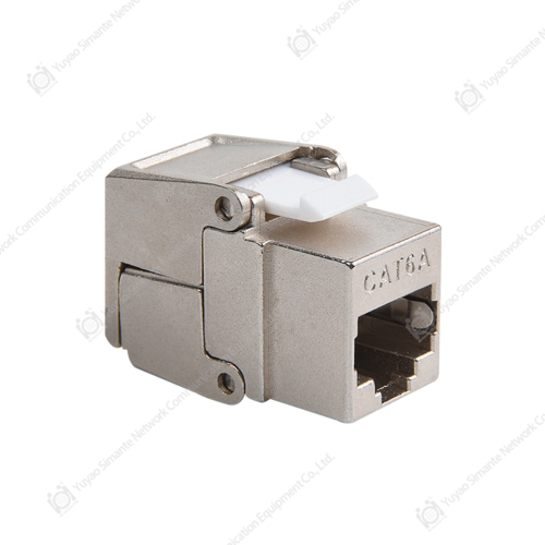
Keystone jacks are a common weak point in field terminations. The jack may be rated for Cat6 or Cat6A, but the performance depends on pair management, conductor seating, and strain relief. A tester with a clear wiremap display and a length reading can help separate a bad termination from a cable break. If the length is correct and the wiremap is clean but the performance result is marginal, the next check is usually the jack and the patch cord, not the bulk cable.
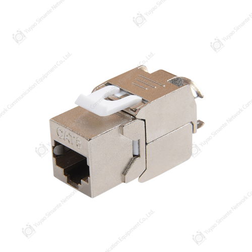
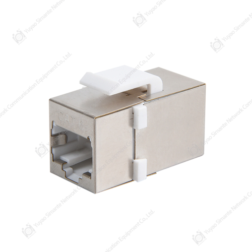 CAT6 Keystone Jacks in Shielded, UTP, and Toolless VariantsCompare shielded, UTP, toolless, and angled CAT6 jacks with 110 or Krone IDC termination when field results point to termination rather than bulk cable.View Product →
Patch panels create a similar effect at the other end of the link. A high-density panel can look neat from the front and still have a poor rear termination on one port. When a tester reports a failure on a single port, compare it with a neighboring port on the same panel. If the neighboring port passes with the same patch cord and the same test setup, the fault is more likely in the panel termination or the horizontal cable than in the tester.
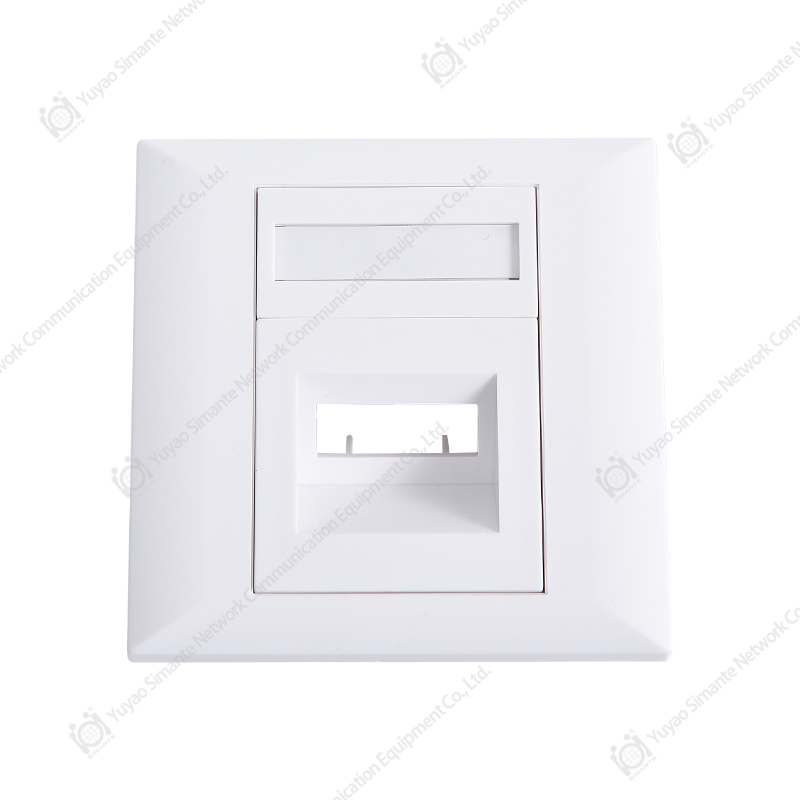
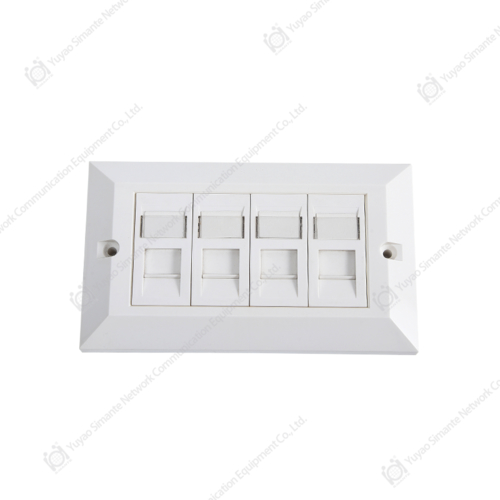
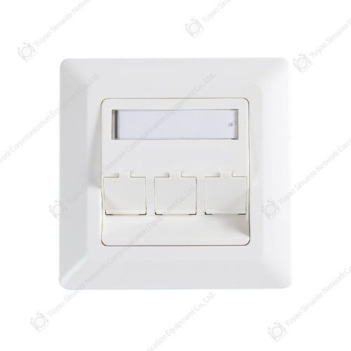
Faceplates and surface mount boxes are mechanical parts, but they influence the link as well. A faceplate that puts strain on the jack, or a surface box that bends the cable beyond its bend radius, can create a return loss problem that only appears after the cover is installed. Test the link with the final assembly in place when the project allows it. A copper cable tester used before the cover goes on may miss a problem that appears after the cable is dressed into the box.
For buyers sourcing both testers and connecting hardware, it helps to work with a manufacturer that understands the whole copper system. A supplier who can explain jack termination, patch panel wiring, and test limits is more useful than a supplier who only quotes a price per piece. That is especially true for a wholesaler building a kit for contractors, because the kit should include testers, patch cords, jacks, and panels that are compatible in the field.
PoE, Shielded Cables, and the Faults That Do Not Show Up in a Wiremap
Power over Ethernet has made copper testing more important, not less. A link that carries data perfectly at low power may fail when a powered device draws current. The symptoms can be subtle: a camera reboots at night, an access point drops under load, or a PoE phone works on one port but not another. A basic wiremap tester may show all eight conductors correct and still miss the cause.
One common issue is resistance unbalance. If one conductor in a pair has a higher resistance than its partner, the link may pass a simple continuity check but produce excessive heating or voltage drop under PoE load. A tester with resistance measurement and PoE load testing can reveal that condition. Another issue is a poor crimp or insulation displacement connection that changes resistance when the cable warms up. These faults are difficult to find with a static test, so a tester that applies a load or records resistance values is more informative.
Shielded cables add another layer. On an F/UTP or S/FTP link, the shield is not a data conductor, but it still needs continuity and proper bonding. If the drain wire is open at one end, the link may pass wiremap and still behave poorly in an electrically noisy environment. A tester that checks shield continuity and can identify the shield path is useful for industrial sites, hospitals, and dense wireless deployments where electromagnetic interference is a real concern.
PoE also changes the acceptance question. The team may need to confirm not only that the link meets a cabling category, but also that the channel can deliver the required power class over the installed length. That is not a reason to skip certification. It is a reason to add a PoE check to the acceptance procedure and to record the result with the link ID. If a device later fails, the record shows whether the link was tested under load and what the tester reported.
For a contractor, the practical rule is simple: do not use a continuity tester as the only tool on a PoE project. Use a copper cable tester that can show wiremap, length, resistance, and PoE behavior, and keep a known-good reference link for comparison. That reference link is often more useful than a long list of specifications because it gives the technician a baseline under the same conditions.
A Field Test Procedure That Reduces Callbacks
A tester is only as good as the procedure around it. The following sequence is a practical field routine for copper links. It is not a substitute for the project specification, but it helps a team produce consistent results and avoid repeated visits.
- Confirm the link identity before testing. Match the outlet label, patch panel port, and floor plan. A correct test on the wrong port is still a wrong result.
- Inspect the termination. Check pair untwisting, conductor seating, strain relief, and bend radius at the jack, panel, and faceplate.
- Test with the final patch cords where possible. A known-good reference cord helps separate a link failure from a cord failure.
- Run wiremap and shield continuity first. Resolve opens, shorts, crossed pairs, and split pairs before moving to performance tests.
- Check length and fault distance. Compare the reading with the design length and the cable library setting.
- Run the required performance test for the category and application. Save the result with the link ID and the tester settings.
- Add a PoE check when the link will power a device. Record the result and note the device class or load condition.
- Retest after any remediation. Do not edit a failed result into a pass; create a new record so the history is clear.
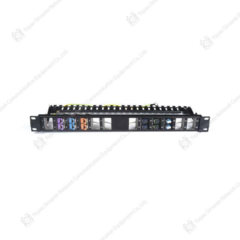
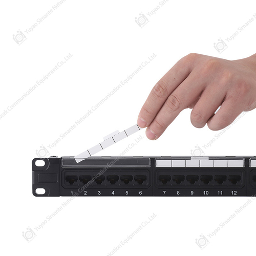 CAT6 Patch Panels for Rack-Mounted Structured CablingReview 0.5U to 2U UTP and shielded CAT6 panels with 110/Krone IDC termination when matching cabling hardware and test setup across a project.View Product →
This procedure also helps when a project uses a mix of Cat6 and Cat6A hardware. The tester settings, the reference cords, and the link limits must match the category under test. A Cat6A link tested with a Cat6 adapter or a Cat5e reference cord may produce a result that is technically valid for the wrong setup. Keep adapters and reference cords labeled, and check them when a result looks inconsistent with the rest of the floor.
For a project manager, the most valuable output is not a single pass result. It is a set of records that shows what was tested, with what settings, by whom, and when. A copper cable tester with storage and export functions makes that possible. If the tester has no storage, the team should still keep a manual log with link ID, test type, result, and remediation notes. The log is what protects the contractor when a link is questioned later.
Procurement Checklist for Distributors and Contractors
Buying a copper cable tester is a procurement decision as much as a technical one. The lowest price per unit can be misleading if the tester lacks the adapters, firmware support, or calibration path needed for the projects in hand. The following checklist helps a contractor or a distributor compare offers on the points that affect field use.
- Test functions: confirm wiremap, length, tone, TDR, PoE, and performance capability against the actual project mix.
- Category support: check declared support for Cat5e, Cat6, Cat6A, and Cat7 links, including shielded variants.
- Connector and adapter range: verify that the tester accepts the plugs and adapters used in the region and on the project.
- Calibration and service: ask about calibration intervals, service turnaround, and firmware updates.
- Result management: check storage, export format, link labeling, and reporting software.
- Field durability: review battery life, case protection, display readability, and operating temperature.
- Training and documentation: request a quick-start guide and training material for new technicians.
- Supplier support: confirm that the manufacturer or wholesaler can supply replacement adapters and reference cords.
 Crimp and Termination Tools for Network Cabling InstallationsReview crimp and termination tools for 8P modular, 90-degree, and 180-degree connectors when building a cabling kit around tester and connector needs.View Product →
For a distributor, the tester should be evaluated as part of a cabling kit. The kit may include a copper cable tester, reference patch cords, a tone probe, a crimp tool, and a selection of keystone jacks and faceplates. A contractor who buys the tester alone may return for the accessories later, but a kit that matches the local project mix is easier to sell and easier to support. The same logic applies to a wholesaler serving multiple installers: the product mix should reflect the categories and connectors that move together.
When comparing a manufacturer or supplier, ask for a clear statement of what the tester does and does not measure. A good supplier will explain the difference between continuity, qualification, and certification instead of treating them as synonyms. That kind of support reduces returns and builds trust with contractors who need a tool they can rely on across projects. It also helps the buyer avoid overpaying for functions that will never be used or underbuying for a project that requires formal reports.
Common Mistakes When Buying or Using a Copper Cable Tester
Most tester problems are not caused by a defective instrument. They come from a mismatch between the tester and the job, or from a test setup that was not controlled. The table below lists common mistakes and the practical correction.
| Mistake | What happens | Practical correction |
|---|---|---|
| Using a continuity tester for data acceptance | A link passes continuity but fails wiremap or performance | Use a tester that reports wiremap, length, and the required performance check |
| Testing with an unknown patch cord | A good link is marked bad, or a bad cord is left in service | Keep labeled reference cords and test the cord separately |
| Ignoring shield continuity | A shielded link passes data but performs poorly in noisy areas | Check shield continuity and bonding as part of the wiremap test |
| Skipping PoE load checks | A device reboots or drops under power even though data tests pass | Add resistance and PoE checks when the link will power equipment |
| Not saving results | Handover disputes and no history for later faults | Store link ID, test type, settings, and result at the time of test |
Another common mistake is assuming that a higher category tester automatically solves a lower category problem. A certification tester is valuable, but it will not fix a jack terminated with excessive untwisting or a patch panel with a loose connection. The tester identifies the symptom; the technician still has to correct the workmanship. That is why training and a clear acceptance procedure matter as much as the instrument specification.
For a buyer, it is also a mistake to ignore the cost of ownership. Calibration, adapters, reference cords, repairs, and training all affect the real cost of a tester over its service life. A lower-cost unit that cannot be calibrated or supported may cost more in downtime than a higher-cost unit with a clear service path. The right comparison includes the full kit and the support behind it.
FAQ: Copper Cable Tester Questions
What is the difference between a copper cable tester and a certifier?
A copper cable tester is a broad term. It can mean a simple continuity checker, a wiremap tester, a tone and probe kit, or a qualification unit. A certifier is a specific class of tester that measures against a named cabling standard and produces a formal report. If the project requires a warranty handover or third-party acceptance, a certifier is usually the correct tool. If the job is fault finding or a quick service check, a simpler tester may be sufficient.
Can a copper cable tester find a break behind a wall?
Yes, if it has a length or time-domain reflectometry function. The tester sends a pulse down the cable and estimates the distance to the fault based on the reflection. The reading depends on the velocity of propagation setting and the cable type, so the technician should select the correct cable library entry. A distance reading is an estimate, not an X-ray image, but it is often enough to decide which section of wall or ceiling to open.
Do I need a tester for Cat6A and shielded links?
You need a tester that matches the link you are accepting. Cat6A links have tighter performance requirements than Cat5e or Cat6, and shielded links add shield continuity and bonding checks. A basic wiremap tester may confirm pin order but will not tell you whether the link has enough performance headroom. For project acceptance, use a tester rated for the category and the shielded configuration. For service work, a wiremap and length tester may still be useful for fault location.
Why does a link pass wiremap but fail PoE?
Wiremap checks conductor order and continuity, but it does not fully describe resistance, heating, or load behavior. A link can have correct pin order and still have a high-resistance connection, an unbalanced pair, or a damaged conductor that behaves differently under current. A tester with resistance measurement and PoE load testing can expose that condition. If a powered device is unstable, test the link under load and compare it with a known-good port.
How often should a copper cable tester be calibrated?
The interval depends on the manufacturer, the tester class, and the project requirements. Certification testers usually have a defined calibration cycle because their results may be used for formal acceptance. Simple continuity and wiremap testers may have a longer or simpler check process. Ask the supplier for the recommended interval and keep the calibration record with the tester. If a result looks inconsistent across known-good links, check calibration and reference cords before blaming the cable.
What should a contractor ask a supplier before buying?
Ask what the tester measures, which categories and shielded links it supports, what adapters are included, how results are stored, and how calibration and service are handled. A good supplier will explain the difference between continuity, qualification, and certification instead of treating them as the same function. For a distributor or wholesaler, ask whether replacement adapters, reference cords, and training materials are available. Those details matter more than a single headline specification.
Related Resources
For buyers who want to compare tester functions with the rest of the copper system, the site resources below provide useful context. They are written for contractors, distributors, and project teams that need practical information rather than a catalog list.
- Learn about the manufacturer background and production capability behind the copper and fiber product lines.
- Read the structured cabling product overview for copper and fiber systems.
A copper cable tester is most useful when it is part of a complete cabling kit: the right jacks, patch panels, patch cords, faceplates, and tools, backed by a supplier who understands how they work together. That is the practical link between a test result and a reliable installation.