Español
 عربى
عربى русский
Content
- 1 What Makes a Keystone Jack "Cat7 Compatible"
- 2 Shielding Types: Why S/FTP Is Non-Negotiable for Cat7
- 3 GG45 vs. TERA: Choosing the Right Cat7 Connector Format
- 4 Termination Style: Tool-Less vs. Punch-Down
- 5 Conductor Gauge Compatibility: Matching the Jack to Your Cable
- 6 Wiring Configuration: T568A vs. T568B
- 7 Key Specifications to Check Before Buying
- 8 Common Installation Mistakes That Degrade Cat7 Performance
- 9 When to Choose Cat7 Keystone Jacks vs. Cat6A
- 10 Testing Your Cat7 Termination After Installation
Choosing the best Cat7 keystone jack comes down to three core factors: shielding type (STP vs. FTP), connector termination style (tool-less vs. punch-down), and compatibility with your cable's conductor gauge. Get those right, and your network will consistently hit Cat7's rated 600 MHz bandwidth over runs up to 100 meters. The sections below break down every decision point with specific specs, comparisons, and real-world guidance.
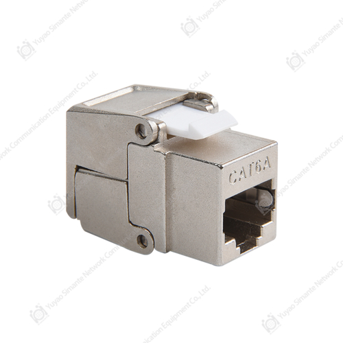
What Makes a Keystone Jack "Cat7 Compatible"
Cat7 is an ISO/IEC 11801 Class F standard, not a TIA/EIA standard, which means the specification details differ from the more common Cat5e/Cat6 classifications. A genuine Cat7 keystone jack must meet the following minimum performance thresholds:
| Parameter | Cat6A | Cat7 | Cat7A |
|---|---|---|---|
| Bandwidth | 500 MHz | 600 MHz | 1000 MHz |
| Max Data Rate | 10 Gbps | 10 Gbps | 40–100 Gbps |
| Shielding Requirement | Optional | Mandatory (S/FTP) | Mandatory (S/FTP) |
| Connector Type | RJ45 | GG45 or TERA | GG45 or TERA |
Notice that Cat7 mandates full shielding on every component, including the keystone jack itself. Any jack labeled "Cat7" but lacking individual pair shielding plus an overall braid does not meet the standard, regardless of marketing claims.
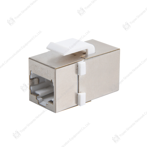
Shielding Types: Why S/FTP Is Non-Negotiable for Cat7
Cat7 cables use an S/FTP (Screened Foiled Twisted Pair) construction: each of the four pairs is individually foil-wrapped, and then the entire bundle is enclosed in a braided screen. A Cat7 keystone jack must continue that shielding path unbroken. Here is what each shielding label actually means:
- FTP / ScTP – Single overall foil only. Suitable for Cat6A, insufficient for Cat7.
- S/FTP – Individual pair foils plus outer braid. Minimum required for Cat7.
- SF/FTP – Individual pair foils plus outer braid plus outer foil. Exceeds Cat7 requirements; commonly used for industrial or high-interference environments.
A broken shield at the termination point acts as an antenna, inviting EMI ingress. In practice, alien crosstalk (AXT) can increase by up to 30 dB if the shield is not properly grounded at the jack — enough to knock a 10GBase-T link offline entirely.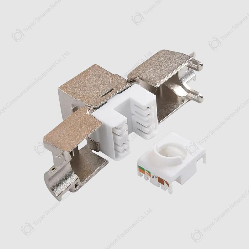
Grounding the Shield Correctly
A shielded jack is only useful if grounded at one end (the patch panel or wall plate side). Grounding at both ends creates a ground loop. Look for jacks with an integrated metal housing that clips directly to a grounded patch panel frame — this eliminates the need for a separate pigtail ground wire and reduces installation errors.
GG45 vs. TERA: Choosing the Right Cat7 Connector Format
Cat7 does not use a standard RJ45 interface. Two connector systems dominate, and selecting the wrong one means buying incompatible patch cords and faceplates:
| Feature | GG45 | TERA |
|---|---|---|
| RJ45 Backward Compatible | Yes | No |
| Max Frequency | 600 MHz | 1000 MHz |
| Contact Points | 8 (+ 4 corner) | 8 |
| Best Use Case | Mixed environments with legacy RJ45 devices | Full Cat7A or purpose-built Cat7 infrastructure |
| Faceplate Availability | Widely available | More limited |
For most home labs and small business deployments, GG45 is the practical choice because existing RJ45 patch cords will still work at Cat6A performance levels while native Cat7 patch cords unlock the full 600 MHz bandwidth.
Termination Style: Tool-Less vs. Punch-Down
How you terminate the cable into the jack affects both installation time and long-term reliability. Cat7 keystone jacks come in two primary termination styles:
Tool-Less (IDC Clip) Termination
Conductors are inserted into labeled slots and a cap is snapped down, cutting and making contact simultaneously. Advantages include faster installation (typically under 2 minutes per jack once practiced), no punch-down tool required, and lower risk of over-driving conductors. The trade-off is slightly higher per-unit cost and less familiar feel to experienced installers used to traditional methods.
Punch-Down (110-Style) Termination
A 110 punch-down tool drives each conductor into an IDC slot. This method is the industry standard in structured cabling and is preferred by professionals doing high-volume patch panel work. For Cat7, ensure your punch-down tool has a low-impact setting — excessive force can damage the foil shield on individual pairs, which degrades the very protection you paid for.
Which Should You Choose?
- DIY or small runs (1–10 jacks): Tool-less is faster and avoids the cost of a quality punch-down tool.
- Professional or large runs (20+ jacks): Punch-down with a calibrated tool delivers more consistent results at scale.
- Retrofit or tight spaces: Tool-less jacks typically have a more compact back profile, easier to work with behind shallow wall boxes.
Conductor Gauge Compatibility: Matching the Jack to Your Cable
Cat7 cables are manufactured in solid-core and stranded variants, each requiring a different IDC contact design:
- Solid conductor (22–24 AWG): Standard for in-wall runs. IDC contacts pierce the insulation cleanly on solid wire. Do not use stranded-only jacks with solid cable — the contact wings can fail to seat properly, causing intermittent continuity.
- Stranded conductor (26–28 AWG): Used for patch cords. Stranded-rated IDC contacts have a wider slot to grip multiple filaments. Using a solid-only jack on stranded cable leads to high contact resistance and signal loss.
- Dual-rated jacks (22–26 AWG): Accept both conductor types. Recommended when you are uncertain of the cable spec or building a mixed environment.
Always verify the AWG range printed on the jack body matches your cable's conductor gauge before purchase.
Wiring Configuration: T568A vs. T568B
Cat7 keystone jacks support both T568A and T568B wiring schemes. The scheme itself does not affect performance — what matters is consistency across every jack, patch panel, and patch cord in the same run. Mixing T568A at one end with T568B at the other creates a crossover cable, which will not work with standard network switches.
- T568B is the most common in North American commercial installations.
- T568A is preferred in government and some international installations, and is required by ANSI/TIA-570-C for residential wiring.
Most Cat7 jacks include color-coded wiring diagrams for both schemes on the body or in the packaging. Choose one and document your choice — this protects anyone doing maintenance years later.
Key Specifications to Check Before Buying
Use this checklist when evaluating any Cat7 keystone jack listing or data sheet:
- Rated bandwidth: Must be ≥ 600 MHz. Anything lower is Cat6A or below.
- Shielding: S/FTP construction with a conductive housing that mates with a grounded panel.
- Insertion loss at 600 MHz: Should be ≤ 0.4 dB per the ISO/IEC 11801 channel model.
- NEXT (Near-End Crosstalk) at 600 MHz: Look for values ≥ 60 dB for margin above the minimum.
- Return loss at 600 MHz: ≥ 15 dB is a practical threshold for 10GBase-T reliability.
- Conductor range: Confirm it matches your cable's AWG (typically 22–24 AWG for solid in-wall Cat7).
- Mating cycles: Quality jacks are rated for ≥ 750 insertions. Budget units often specify only 200.
- Contact plating: Gold-plated contacts (≥ 50 µin) resist oxidation and maintain low contact resistance over time.
Common Installation Mistakes That Degrade Cat7 Performance
Even the highest-spec jack can underperform if installed incorrectly. These are the most frequent errors:
- Excessive untwist at termination: Cat7 allows a maximum of 13 mm (0.5 in) of untwisted conductor at the jack. Exceeding this increases crosstalk and can fail a channel certification test.
- Not maintaining the drip loop on the shield: When routing shielded cable through wall cavities, leave a small loop to prevent moisture from wicking along the braid into the jack housing.
- Overtightening cable ties: Compressing S/FTP cable at bends deforms the individual pair foils, creating impedance discontinuities. Use hook-and-loop fasteners instead of plastic zip ties on Cat7 runs.
- Minimum bend radius violations: Cat7 cable has a minimum bend radius of 8× the cable diameter (typically ~60 mm for 7.5 mm diameter cable). Tighter bends cause reflections that fail return loss tests.
- Mixing shielded and unshielded components: Using a Cat7 jack on an unshielded Cat6A cable, or vice versa, negates the shielding benefit and creates ground discontinuities.
When to Choose Cat7 Keystone Jacks vs. Cat6A
Cat7 infrastructure costs roughly 20–35% more than an equivalent Cat6A installation. That premium is justified in specific scenarios but unnecessary in others:
| Scenario | Recommended Standard | Reason |
|---|---|---|
| Home or small office, 1 Gbps switch | Cat6 or Cat6A | Cat7 overhead unnecessary |
| 10 Gbps backbone, clean environment | Cat6A | Cat6A meets 10GBase-T at lower cost |
| 10 Gbps runs near fluorescent lighting or motors | Cat7 | S/FTP shielding rejects EMI |
| Future-proofing for 25/40 Gbps | Cat7A | 1000 MHz bandwidth required |
| Industrial / manufacturing floor | Cat7 or Cat7A | Heavy EMI environment demands full shielding |
Testing Your Cat7 Termination After Installation
A field tester is the only way to confirm a Cat7 channel meets spec. Basic wiremap testers are insufficient — they do not measure frequency-domain parameters. Use a tester capable of Level IIIe or Level IV accuracy (per IEC 61935-1) to certify a Cat7 channel. Key tests to run:
- Wiremap: Verifies pin continuity and absence of crossed, split, or reversed pairs.
- Insertion loss sweep (up to 600 MHz): Confirms signal attenuation stays within the Cat7 channel limit across the entire frequency range.
- NEXT and FEXT: Crosstalk measurements that catch untwisted conductor issues at the jack termination point.
- Shield continuity: Verifies the drain wire or braid is connected end-to-end without a short to the conductor pairs.
If a channel fails, the most common culprits are excessive untwist at the jack, a damaged pair foil, or a missing shield ground connection — all addressable by re-terminating the jack rather than replacing the cable run.