Español
 عربى
عربى русский
Content
- 1 How Do Patch Panels Work In A Structured Cabling System
- 2 What Are Patch Panels Used For In Commercial And Data Center Networks
- 3 Copper Patch Panels Cat5e Cat6 And Cat6a Options
- 4 Fiber Optic Patch Panels Compared With Copper Patch Panels
- 5 Blank Patch Panels Keystone Patch Panels And Modular Patch Panels
- 6 Port Count And Rack Space Planning For 24 Port Patch Panels
- 7 Faceplates RJ45 Connectors And Keystone Jacks As Structured Cabling Products Components
- 8 Isometric Structure View Of A Rack Mounted Patch Panel
- 9 About Yuyao Simante Network Communication Equipment Co Ltd
- 10 Frequently Asked Questions
How Do Patch Panels Work In A Structured Cabling System
Patch panels work by giving every cable run in a building a fixed, labeled termination point on one side and a set of removable patch cord ports on the other, so that network connections can be organized, tested, and rearranged without disturbing the permanent cabling behind the wall. Each port on a patch panel is wired to a keystone jack or a punch down block that terminates the horizontal cable coming from a wall outlet or ceiling drop, while the front face presents a uniform row of RJ45 or fiber ports that a technician connects to a switch using short patch cords. This structure is a core component of any structured cabling system, because it separates the fixed infrastructure wiring from the flexible, frequently changed connections at the equipment room. A rack mounted patch panel effectively turns a bundle of individually terminated cables into an organized, labeled interface that can be reconfigured from the front of the rack rather than by tracing cables through walls or ceilings. The sections below look at the main patch panel categories, how they compare, and how keystone jacks, faceplates, and RJ45 connectors fit into the same structured cable products family.
What Are Patch Panels Used For In Commercial And Data Center Networks
Patch panels are used for centralizing and managing the termination of copper and fiber cabling in offices, data centers, and residential structured wiring closets, giving network administrators a single, organized location to connect, disconnect, and test network links. In a typical office deployment, horizontal cabling runs from wall outlets and faceplates back to a wiring closet, where each cable is terminated onto a numbered port on a network patch panel; a short patch cord then connects that port to a switch, allowing the connection to be moved or reassigned without re running cable through the building. In data centers, ethernet patch panels and fiber optic patch panels serve a similar role at a larger scale, helping keep server room cabling organized as connections between switches, servers, and cross connect points change over time. Because the patch panel isolates the permanent horizontal cabling from the frequently changed patch cords, moves, adds, and changes can generally be completed at the patch panel itself rather than by accessing cable runs inside walls or raised floors. This is one of the primary reasons structured cabling system designs consistently include a patch panel as a core component rather than terminating cables directly onto network equipment.
Common Roles Patch Panels Perform
- Providing a labeled cross connect point between horizontal cabling and network switches.
- Supporting cable management so bundles of cable are organized rather than tangled.
- Allowing quick testing and troubleshooting of individual cable runs from the front of the rack.
- Simplifying moves, adds, and changes without disturbing the permanent cabling behind walls.
- Meeting cat5e, cat6, cat6a, or fiber transmission standards at a defined, documented interface.
Copper Patch Panels Cat5e Cat6 And Cat6a Options
Copper patch panels are commonly produced to meet cat5e, cat6, or cat6a transmission standards, with the category rating determining the maximum supported data rate and the internal design of the termination points. A cat5e patch panel is typically specified for basic gigabit network deployments, while a cat6 patch panel supports higher bandwidth applications and is widely used in current office and campus network builds. Cat6a patch panels, including shielded options, are designed to support higher frequency transmission with additional shielding to reduce crosstalk, which makes them a common choice for data center and high performance network cabling where sustained throughput matters. Many cat6 patch panel and cat6a patch panel product lines follow the T568A and T568B wiring sequence, with color coded labeling on the termination side to help installers achieve accurate, repeatable punch downs using 110, Krone, or dual type IDC termination methods. Selecting between cat5e, cat6, and cat6a patch panels generally depends on the required data rate, the expected service life of the cabling system, and whether shielding is needed for the installation environment.
The bar chart above presents an illustrative comparison of the general bandwidth range commonly associated with cat5e, cat6, and cat6a patch panel categories rather than a certified test result for any single product. Cat5e patch panels are generally associated with gigabit ethernet performance and remain suitable for many standard office deployments where sustained higher throughput is not required. Cat6 patch panels support a wider practical range, commonly cited as supporting gigabit speeds over longer distances and up to 10 gigabit speeds over shorter, well managed cable runs. Cat6a patch panels are generally positioned to support sustained 10 gigabit performance over the full standard channel length, which is why they are frequently specified in data center and high density network cabling projects. Because actual achievable performance depends on cable length, installation quality, and the complete channel including patch cords and outlets, the category rating of the patch panel is only one part of the overall link performance. Readers planning a structured cabling system should confirm full channel performance against the relevant cabling standard rather than relying on the patch panel category alone.
Fiber Optic Patch Panels Compared With Copper Patch Panels
Fiber optic patch panels serve the same organizational role as copper patch panels but terminate and manage fiber patch cords instead of RJ45 connections, typically using adapter plates that hold LC, SC, or similar fiber connectors in a rack mounted enclosure. Fiber patch panels are commonly selected for backbone links between buildings or floors, for high bandwidth data center interconnects, and for any application where electrical isolation or longer transmission distances are required compared with copper cabling. Because fiber cabling is more sensitive to bend radius and connector cleanliness than copper cabling, fiber optic patch panels often include cable management features such as slack storage trays and splice trays that are not typically found on copper patch panel designs. Ethernet patch panels built for copper cabling remain the more common choice for connecting individual workstations and devices, while fiber patch panels are generally reserved for higher capacity trunk and backbone segments of the network. A structured cabling system frequently uses both copper and fiber patch panels together, with fiber handling backbone and long distance segments and copper patch panels handling the final connection to desktops, access points, and other end devices.
This radar chart illustrates general practical tradeoffs between copper patch panels and fiber optic patch panels across five factors relevant to structured cabling design decisions. Fiber optic patch panels generally score higher on bandwidth capacity and transmission distance, reflecting the physical characteristics of fiber cabling compared with copper cabling over long backbone runs. Copper patch panels tend to score higher on termination simplicity and common desktop use, since RJ45 based terminations are widely standardized and familiar to most cabling installers and network technicians. Electrical isolation is a notable advantage for fiber optic patch panels, since fiber cabling is not affected by electromagnetic interference in the way copper cabling can be. Because most structured cabling system designs use both cabling types for different segments of the network, this comparison is best read as guidance for where each patch panel type fits rather than as a reason to choose one exclusively over the other. Network designers typically select the cabling type first based on distance and bandwidth requirements, then choose the matching patch panel category to support that segment of the installation.
Blank Patch Panels Keystone Patch Panels And Modular Patch Panels
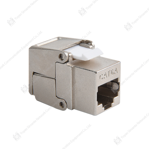
A blank patch panel, sometimes described as a blank keystone 1u patch panel, ships without pre installed jacks, giving installers the flexibility to fit their own choice of keystone jacks, including cat6 keystone jacks or fiber adapters, into the panel openings as needed. This modular patch panel approach is common in structured cable products because it allows a single panel design to support mixed media types, different category ratings, or a combination of data and other connector types within the same rack space. Keystone patch panels rely on a Net Keystone Jack or similar rj45 keystone jack cat6 module snapped into each opening, with the jack itself handling the actual termination of the incoming cable using 110 or similar IDC contacts. Because the keystone jack is a separate, replaceable component, a modular patch panel can be serviced or reconfigured by swapping individual jacks rather than replacing the entire panel, which is a practical advantage in facilities that expect their cabling needs to change over time. Blank and keystone patch panel designs are frequently paired with matching faceplate products at the wall outlet end, creating a consistent keystone based termination system from the work area through to the rack.
Typical Modular Patch Panel Components
- Blank patch panel frame sized to a standard 1u or 2u rack space.
- Keystone jack modules matched to the required category rating, such as cat6 or cat6a.
- Cable management bar or bracket to support strain relief behind the panel.
- Labeling area on the panel face for port numbering and documentation.
- Matching faceplate and rj45 connector components at the work area outlet end.
Port Count And Rack Space Planning For 24 Port Patch Panels
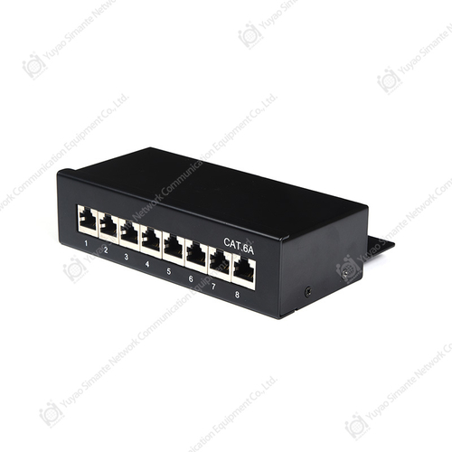
Patch panels are commonly produced in a range of port counts, including compact 8 and 12 port panels for smaller wiring closets and higher density 24 port patch panels and 48 port patch panels for larger installations, with rack space and cable management capacity generally increasing alongside port count. Selecting the correct port count involves balancing current cabling requirements against reasonable future growth, since replacing an undersized patch panel later typically requires re terminating existing cable runs onto a new panel. A 24 port patch panel is a common mid size choice for many office wiring closets, offering enough density for a typical floor or department while remaining manageable within a single rack unit or two rack units of space. Higher port density panels generally require more attention to cable management, since a larger number of patch cords and horizontal cables must be routed, labeled, and dressed without creating excessive strain on individual connections. Network cabling solution designers typically plan port counts based on the number of active outlets served, plus a reasonable allowance for future connections.
This area chart shows an illustrative upward trend in relative rack space and cable management requirements as patch panel port count increases from small 8 port panels through high density 96 port configurations. Smaller panels in the 8 to 12 port range generally fit within compact wiring enclosures and require comparatively simple cable management, making them suitable for small offices or dedicated equipment rooms. The 24 port patch panel range represents a common mid point where cable management brackets and labeling become more important to maintain an organized installation as more connections are added. At higher port counts such as 48 and 96 ports, the trend continues upward more steeply, reflecting the additional cable management, patch cord routing, and rack depth planning typically required at that density. This general pattern is one reason structured cabling system designs often include dedicated cable management panels alongside higher density patch panels rather than relying on the patch panel alone to keep cabling organized. Planners should size both the patch panel and the surrounding rack cable management hardware together rather than considering port count in isolation.
Faceplates RJ45 Connectors And Keystone Jacks As Structured Cabling Products Components
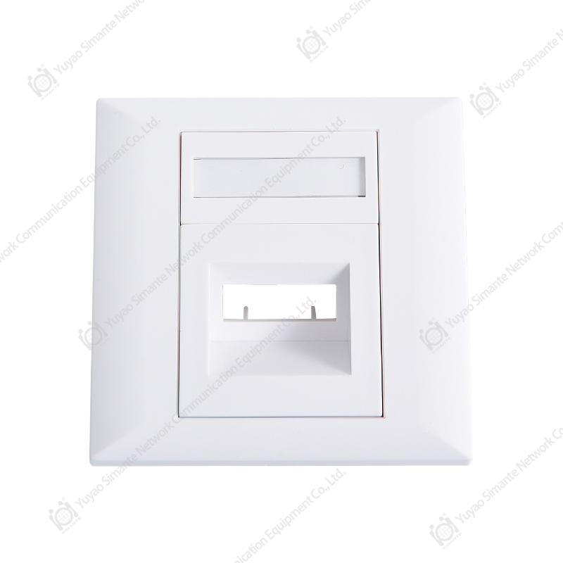
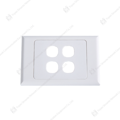
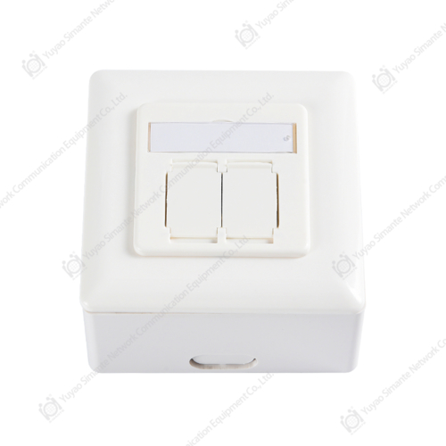
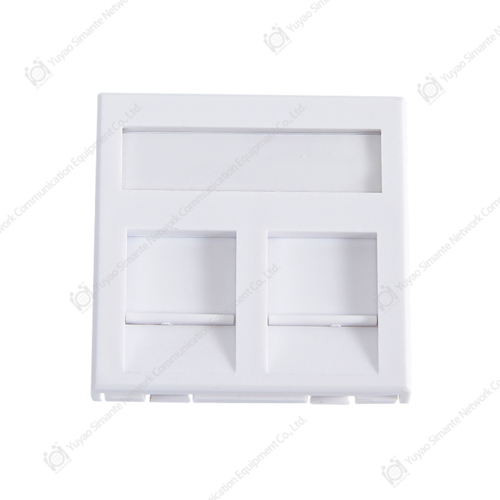
A complete structured cabling system relies on several components working together with the patch panel, including the network face plate at the work area outlet, the keystone jack that terminates the cable inside that faceplate, and the rj45 male connector used on patch cords that connect equipment to the patch panel ports. Faceplate manufacturers typically offer single, double, and multi port configurations to match the number of outlets required at a given work area, with each opening accepting a keystone jack sized to fit standard keystone cutouts. Keystone jack manufacturers commonly produce cat6 and cat6a rated jacks using similar 110 style IDC termination methods found on patch panels, which keeps the termination process consistent whether a technician is working at the faceplate or at the rack. RJ45 connector manufacturers also supply the male plug ends used on patch cords and equipment cords, completing the physical layer chain from the network switch through the patch panel, through the horizontal cable, and out to the keystone jack and faceplate at the work area. Using components from a consistent structured cable products family, matched to the same category rating throughout the channel, helps maintain predictable performance from the patch panel to the final work area outlet.
| Component | Typical Category | Termination Method | General Use Case |
|---|---|---|---|
| Cat6 Patch Panel | Cat6 | 110 or Krone IDC | General office and campus network cabling |
| Blank Keystone 1u Patch Panel | Mixed, User Fitted | Depends on jack fitted | Mixed media and modular installations |
| Fiber Optic Patch Panel | Single or Multimode Fiber | Fiber Adapter and Splice | Backbone and data center interconnects |
| Keystone Jack | Cat6 or Cat6a | 110 IDC | Faceplate and modular patch panel termination |
| Network Faceplate | Single to Multi Port | Accepts Keystone Jack | Work area wall outlet termination |
Isometric Structure View Of A Rack Mounted Patch Panel
The isometric diagram below outlines the general structure of a rack mounted patch panel, showing the front row of RJ45 ports, the rear termination area where keystone jacks or IDC contacts connect to horizontal cable, and the mounting ears used to secure the panel into a standard rack frame. The front face presents a uniform row of numbered ports, which is the interface a technician uses when connecting patch cords to network switches or other equipment. The rear of the panel holds the termination points, shown here in simplified form, where each incoming cable is punched down or seated into its corresponding port position. The mounting ears on either side allow the panel to be secured into a standard 19 inch rack using ordinary rack screws, keeping the patch panel aligned with other rack mounted equipment. Viewing the panel in this simplified three dimensional form helps clarify how the front facing ports and rear facing terminations serve two distinct but connected functions within the same patch panel.
This isometric SVG illustration is a simplified representation intended to communicate function rather than to serve as a manufacturing drawing. The front row of dark ports represents the RJ45 or fiber adapter positions a technician uses to connect patch cords, shown here as a uniform row across the panel face. The rear panel section shown in the diagram represents the general area where each port connects to horizontal cable through a keystone jack or IDC contact, though the specific termination style varies by product design. The mounting ears on either side of the panel body represent the hardware used to secure the panel into a standard rack frame alongside other network cabling solution components. Actual port spacing, labeling, and termination details should always be confirmed against the current specification sheet for the specific patch panel model being installed.
About Yuyao Simante Network Communication Equipment Co Ltd
Yuyao Simante Network Communication Equipment Co., Ltd. is a professional manufacturer of network cabling solutions and optical fiber products, integrating design, development, sales, and service into a single structured cable products operation. In nearly 20 years of service, the company has focused on meeting customer needs through technical expertise, aiming to provide value from the earliest stages of a project through ongoing communication and support. Based on a mature research and development system, Simante maintains quality stability at the design source, supporting consistent performance across its patch panel, keystone jack, and faceplate product lines. The company employs more than 10 engineers and over 30 full time technical personnel who continue to provide professional value in their roles, working on improving product quality and promoting ongoing product updates across categories including cat6 and cat6a patch panels, fiber optic patch panels, keystone jacks, faceplates, and rj45 connector products used throughout structured cabling system installations.
Frequently Asked Questions
Q1: What are patch panels used for.
A1: Patch panels are used to organize and terminate network cabling at a central point, giving technicians a labeled interface to connect, disconnect, and test network links without disturbing the permanent cabling behind walls or ceilings.
Q2: What is the difference between a copper patch panel and a fiber optic patch panel.
A2: A copper patch panel terminates RJ45 based cabling such as cat5e, cat6, or cat6a cable, while a fiber optic patch panel manages fiber cabling using adapter plates for connectors such as LC or SC, commonly used for backbone and data center links.
Q3: How does a blank keystone patch panel differ from a pre loaded patch panel.
A3: A blank keystone patch panel ships without jacks installed, allowing installers to fit their own choice of keystone jacks, while a pre loaded patch panel comes with jacks or ports already fixed in place for a specific category rating.
Q4: How many ports should a patch panel have.
A4: Port count is generally chosen based on the number of active network outlets served plus a reasonable allowance for future growth, with common options including 8, 12, 24, and 48 port patch panels depending on the size of the installation.
Q5: What wiring standard do patch panels typically follow.
A5: Most copper patch panels follow the T568A or T568B wiring sequence, with color coded labeling on the termination side to support accurate and consistent punch down terminations.