Español
 عربى
عربى русский
Content
- 1 Copper Cable Color Code Basics: Color Is Pinout, Not Decoration
- 2 T568A vs T568B: Same Cable, Two Pin Maps
- 3 The 25-Pair Binder Color Code Behind the Patch Panel
- 4 Where Copper Cable Color Codes Go Wrong on Live Jobs
- 5 Patch Cords, Male Connectors and the Colors You Never See
- 6 Reading the Copper Cable Color Code at the Panel, the Jack and the Outlet
- 7 Verification: Proving the Color Code Before Handover
- 8 What to Ask a Manufacturer or Supplier Before Ordering in Volume
- 9 FAQ: Copper Cable Color Code Questions Installers Ask Most
- 9.1 Is T568A or T568B the correct copper cable color code?
- 9.2 What happens if one end of a link is T568A and the other is T568B?
- 9.3 How much untwisted conductor is acceptable at the termination point?
- 9.4 What is the color code for a 25-pair copper cable?
- 9.5 Do shielded cables use a different color code?
- 9.6 Can I mix CAT5E and CAT6 components in the same link?
- 9.7 Why does my wire map test show split pairs when the colors look correct?
- 10 Bringing It Together: Standardize, Label, Verify
- 11 Related Resources
Picture a telecom room the afternoon before handover. Ninety-six copper links are terminated, ninety-five pass the wire map test, and link 14 comes back with pairs 1-2 crossed. The cable is genuine, the jacks are new, and the tester has just been calibrated. What went wrong is simpler than anyone wants to admit: the technician who punched that jack down read the copper cable color code in a different order than the rest of the crew.
Here is the conclusion before the detail. A copper cable color code is not decoration and it is not a branding choice. It is the physical layer pin assignment written into the insulation. The colors tell you which twisted pair must land on which contact, and the pair has to stay intact from the patch panel all the way to the outlet. Once color is treated as pinout rather than appearance, most termination rework disappears before it happens.
What follows covers the two industry wiring schemes, the 25-pair binder color code that runs behind the patch panel, the failure patterns that appear when codes get mixed on a live job, and the practical checks worth running before a wall gets closed up.
The copper cable color code is a pin map, not a cosmetic detail. Agree on one scheme, write it on the drawing, and every termination after that becomes a repeatable task instead of a judgment call.
Copper Cable Color Code Basics: Color Is Pinout, Not Decoration
A standard four-pair unshielded twisted pair cable carries eight conductors. Each pair is made of two insulated wires that are twisted around each other at a controlled rate, and each pair is identified by color. In the most common construction, one conductor is a solid color and its partner is predominantly white with a stripe of that same color running along it. Some premium cables use a solid color plus a contrasting stripe instead, and some use two clearly separated shades, but the logic is identical: a pair is a pair, and the two conductors that twist together must terminate on two contacts that belong to the same signal path.
The terminology trips people up at first. The "tip" conductor is the one that carries the signal into the contact, and the "ring" conductor carries it back out. In eight-position modular cabling, the industry convention is that the striped or lighter conductor is usually the tip and the solid conductor is usually the ring, but what actually matters is that both members of a pair land on the correct pair of pins. Swapping tip and ring inside a single pair is far less harmful than splitting a pair across two different pin positions.
Why is that split so damaging? Because twisting is not cosmetic either. The twist rate controls the characteristic impedance of the pair and, more importantly, it cancels the electromagnetic field that the signal generates. When a conductor is pulled out of its twist and run alongside a conductor from a different pair, that cancellation stops. Near-end crosstalk rises sharply, return loss degrades, and a link that looks perfect on a basic continuity tester can fail a certification test by a wide margin. In field practice, the untwisted section at the termination point is usually kept to roughly 13 mm or less, and that number is worth writing on the tool box.
The standards behind all of this are the familiar ones: the TIA/EIA-568 series in North America and ISO/IEC 11801 internationally. Both define the same color-to-pin relationships, and both allow two wiring schemes. Everything downstream, from keystone jacks to patch panels to faceplate labels, is built around those two schemes.
Color identifies the pair; the twist protects the signal. Keep the pair together, keep the untwisted section short, and the color code does its job automatically.
T568A vs T568B: Same Cable, Two Pin Maps
The two schemes are closer than most people expect. They differ in exactly one place: the positions of the green pair and the orange pair on pins 1, 2, 3 and 6. The blue pair stays on pins 4 and 5, and the brown pair stays on pins 7 and 8 in both schemes. That is the whole difference, and it is small enough that crews sometimes assume it does not matter. It matters a great deal when the two ends of the same link disagree.
| Pin | T568A conductor | T568B conductor | Pair number |
|---|---|---|---|
| 1 | White / Green | White / Orange | 3 in A, 2 in B |
| 2 | Green | Orange | 3 in A, 2 in B |
| 3 | White / Orange | White / Green | 2 in A, 3 in B |
| 4 | Blue | Blue | 1 |
| 5 | White / Blue | White / Blue | 1 |
| 6 | Orange | Green | 2 in A, 3 in B |
| 7 | White / Brown | White / Brown | 4 |
| 8 | Brown | Brown | 4 |
Read the table from the perspective of the person holding the plug with the clip facing away. In T568A the green pair occupies the first two positions and the orange pair occupies positions 3 and 6. In T568B it is the reverse. Everything else is identical, which is why a single wrongly terminated end is so easy to miss on a visual inspection and so easy to catch on a wire map test.
Consistency Beats Preference
The honest answer to "which one is better" is that neither scheme outperforms the other electrically. Both support the same categories and the same applications when they are applied consistently. The choice is normally driven by regional habit and by the specification the client wrote. In North America, commercial projects commonly specify T568B, while some government, education and residential specifications still call for T568A. In many European and Asian markets the balance shifts the other way. What matters is not the winner of that argument but that the whole site, from the entrance facility to the last outlet, follows one rule.
A link with T568A on one end and T568B on the other is not a failed link in the electrical sense. It is a crossover link. Pins 1 and 2 are swapped with pins 3 and 6, so a signal transmitted on one pair arrives on a different pair at the far end. Some equipment tolerates that automatically, and some does not. Even when it works, the installation is not what the drawing says, and the next technician who touches it will inherit a puzzle. Certification testing against a documented scheme is what prevents that inheritance.
A practical habit that costs almost nothing: print the chosen scheme on the inside of the faceplate or on the cable label at the panel, and keep one reference drawing in the telecom room. Six months later, during a move-add-change, that single sheet of paper saves an hour of guessing.
Pick T568A or T568B once, document it, and apply it on both ends of every link. Mixing schemes inside one link turns a straight-through channel into an undocumented crossover.
The 25-Pair Binder Color Code Behind the Patch Panel
The horizontal cabling in a commercial building is usually four-pair cable, but the backbone and the entrance side are a different world. There, copper arrives as 25-pair, 50-pair or 100-pair bundles, and each conductor still has to be identifiable at a punch-down block or a high-density patch panel. That is where the binder color code takes over from the eight-conductor scheme.
The system is elegant once you see the pattern. It uses five tip colors and five ring colors. The tip sequence runs white, red, black, yellow, violet. The ring sequence runs blue, orange, green, brown, slate. Combine them in nested loops and you get exactly 25 unique pair combinations, which is why 25-pair is the natural building block of copper backbone cable. Each group of five pairs is then wrapped in a colored binder that names the group, and the binder colors themselves follow the same five-color sequence.
| Binder group | Binder color | Pair numbers | Conductor colors inside the group |
|---|---|---|---|
| 1 | Blue | 1 to 5 | White/Blue, White/Orange, White/Green, White/Brown, White/Slate |
| 2 | Orange | 6 to 10 | Red/Blue, Red/Orange, Red/Green, Red/Brown, Red/Slate |
| 3 | Green | 11 to 15 | Black/Blue, Black/Orange, Black/Green, Black/Brown, Black/Slate |
| 4 | Brown | 16 to 20 | Yellow/Blue, Yellow/Orange, Yellow/Green, Yellow/Brown, Yellow/Slate |
| 5 | Slate | 21 to 25 | Violet/Blue, Violet/Orange, Violet/Green, Violet/Brown, Violet/Slate |
In the example above, the convention is written as tip color first and ring color second, so White/Blue means a white tip conductor paired with a blue ring conductor. Some drawings reverse the order, which is a common source of confusion during handover documentation. It is worth agreeing on the wording before the first block gets punched.
Larger cables simply repeat the pattern. A 50-pair cable contains two 25-pair groups, each with its own binder wrap, and the two groups are usually distinguished by an additional supergroup binder in blue or orange. A 100-pair cable contains four, and the supergroup binders cycle through the same five-color sequence again. Once the pattern clicks, a technician can identify pair 63 in a 100-pair bundle without a tone generator, just by opening the bundle and counting binders.
Where this pattern meets hardware is at the back of the rack. A patch panel with printed color bars next to each insulation displacement contact removes almost all of the guesswork, because the label on the block and the color in your hand should match line for line. Panels that print the code clearly, in both schemes, save measurable time during large terminations.
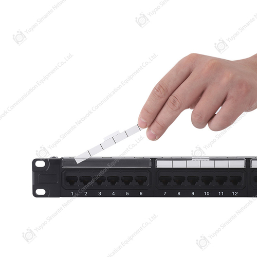 CAT6 Patch Panel ManufacturersSMT-2010D24C6 1U24 Port 180 Degree UTP CAT6 Patch PanelView Product →
For projects that mix backbone terminations with high-density patching, the layout of the rear termination block and the legibility of the color printing matter more than most buyers expect. A panel that is easy to read at arm's length under poor lighting is a genuine productivity feature, not a marketing line.
The 25-pair binder code is a five-by-five grid: five tip colors crossed with five ring colors give 25 pairs, and the binder wrap simply repeats that sequence for larger cables.
Where Copper Cable Color Codes Go Wrong on Live Jobs
Most failures are not caused by defective materials. They are caused by a decision made in thirty seconds at the back of a rack. The four patterns below account for the overwhelming majority of wire map failures on commercial installations, and each one has a recognizable signature.
Split Pairs
A split pair happens when one conductor from pair A and one conductor from pair B are terminated as if they formed a pair. On a wire map test it usually appears as a pair that is "correct" on one end and reversed on the other, or as an unexpected crossover between two pairs. The colors at the jack can look plausible at a glance, which is exactly why it survives a visual check. The fix is re-termination, not a new cable.
Mirrored or Reversed Pin Order
Terminating pins 1 through 8 from the wrong side of the jack produces a fully mirrored pin sequence. The link may still negotiate a low-speed connection, which makes the fault harder to notice until a higher-speed device is connected. This is common when a crew switches between jacks from different suppliers, because the contact numbering printed on the plastic is not always oriented the same way.
Faded or Inconsistent Jacket Printing
Low-cost cable sometimes prints pair identifiers in ink that fades or smears after a few months on a warm rack. Two reels from the same supplier, ordered at different times, can also show noticeably different shades of the same nominal color. In a large pull, a technician who has been reading "white with a blue stripe" all morning can easily mistake a faint stripe for a different color in poor light. This is a supplier consistency issue, not a craftsmanship issue.
Shielded Cable and Drain Wires
Shielded copper cable keeps the same four-pair color code as unshielded cable, but adds a foil or braid shield and a drain wire. The drain wire is usually bare or tinned copper and must be terminated to the connector housing, not to a signal contact. Crews who are used to unshielded work sometimes place the drain wire into an unused contact out of habit, which creates a short or an unexpected ground path.
To make the distribution of these problems easier to see, the chart below shows an illustrative weighting of what installers most often find when a copper link fails a wire map test. The figures come from typical field patterns rather than a published study, and they are meant to show relative weight rather than precise statistics.
Illustrative breakdown of wire map failures found on copper links
Illustrative figures used to show relative weight, not results from a published study.
Two of the five categories point straight back to the hardware rather than to the installer. Split pairs and reversed pin order are mostly training and documentation problems, and a jack whose contacts are clearly numbered helps solve both. Faded printing and nicked conductors are more often a materials and tooling issue, which is why buyers who care about long-term reliability tend to look at jack design, strain relief and the quality of the insulation displacement contacts rather than at the price per piece alone.
From a product perspective, the components that reduce these errors are unglamorous. A keystone jack with an unambiguous color guide molded into the housing, a crimp tool with a controlled stroke, and a cable manager that keeps bundles dressed away from sharp metal edges all contribute more to a passing link than any single premium component. When a supplier can describe those details concretely, that is usually a sign the factory understands field conditions rather than only the catalog.
| Symptom on the tester | Likely root cause | Corrective action |
|---|---|---|
| Pairs 1-2 and 3-6 report as split pairs | One end wired T568A, the other T568B | Re-terminate the end that does not match the drawing |
| Full mirror of the pin sequence | Jack terminated from the wrong side | Re-punch following the numbering on the housing |
| Length passes, crosstalk fails badly | Excessive untwisted conductor at the contact | Redo the termination with a shorter untwisted section |
| Intermittent open on one conductor | Conductor nicked during jacket removal | Cut back and re-terminate on fresh cable |
| Random failures across a whole pull | Faded or inconsistent jacket printing | Verify supplier batch consistency before the next order |
Split pairs and mirrored pin order are the two failures a wire map test catches immediately, and both are caused by the color code being read differently at each end of the same link.
Patch Cords, Male Connectors and the Colors You Never See
Once a link leaves the panel and heads to a workstation or a switch, the conductor colors disappear inside a molded plug. Factory-made patch cords are assembled to one scheme and tested as a unit, so the color code is fixed at the factory rather than at the site. That is precisely why they are worth buying rather than building on a bench.
What the buyer does see is the color of the jacket itself. Different jacket colors are a widely used identification convention: one color for the data outlet, another for voice, another for the uplink between switches. There is no universal rule here, and any site can define its own. The important point is that jacket color and conductor color are two separate systems, and confusing them leads to a different kind of mistake, where a cord is chosen for its color and assumed to match a wiring scheme it has nothing to do with.
Field-made patch cords are where the hidden color code becomes visible again. With a transparent plug, the conductor order is fully exposed, and anyone building cords should be able to read T568B from left to right without hesitation. With an opaque plug, an incorrect order simply becomes an invisible fault. The failure rate for hand-crimped cords rises quickly in volume production, which is why most projects treat factory cords as consumables rather than as a workshop task.
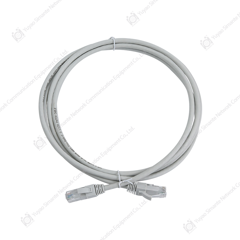 Patch Cord ManufacturersCAT.6A UTP Patch Cord Unshielded Patch CordView Product →
Cord construction details that matter more than most buyers expect include the strain relief geometry, the plating on the contacts and the amount of untwisted conductor inside the plug. A cord that passes a continuity check but shows elevated return loss will cause intermittent link problems that are extremely difficult to trace later, particularly on longer channel runs where the cord is only one of several components in the budget.
Jacket color is an identification convention chosen by the site; conductor color is a fixed standard. Treating the two as the same system is how patch cords end up mismatched with the links they serve.
Reading the Copper Cable Color Code at the Panel, the Jack and the Outlet
The color code appears in three physical places on every permanent link, and each one has its own reading convention. Getting all three aligned is what turns a wiring scheme on paper into a working channel.
At the patch panel, the color guide is printed directly beside the insulation displacement contacts. Most panels show both schemes side by side, or print a single scheme chosen at the factory. During termination, the correct habit is to read the panel label rather than to rely on memory. On rear-facing 110 style blocks, the pairs are arranged in rows, and the order of the pairs on the block does not always match the order of the pairs in the cable jacket. The label resolves that difference.
At the keystone jack, the guide is usually a sticker on the side of the housing or a molded color chart. The critical detail is orientation: a jack that shows T568A on one side and T568B on the other must be read with the correct side facing the installer. This is one of the most common sources of a mirrored termination on an otherwise careful job.
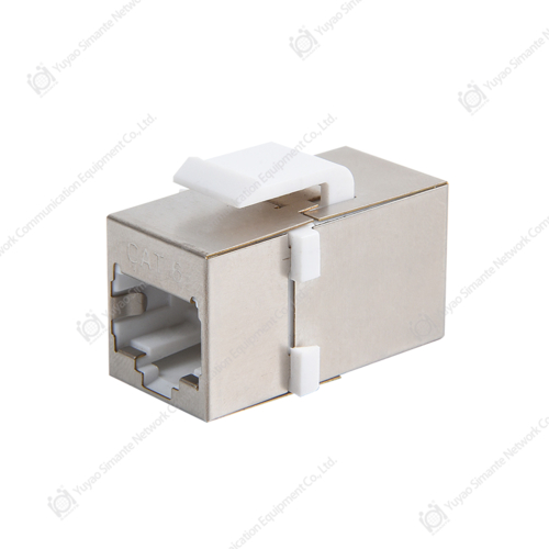 Cat6 Keystone Jack ManufacturersSMT-1034T8C6-FTP Shielded CAT6 Inline CouplerView Product →
Jacks that are designed for tool-free termination can reduce assembly time noticeably on large projects, but the trade-off is that the installer has less tactile feedback than with a punch-down tool. In both designs, the component that prevents field errors is a legible, unambiguous color guide that stays readable under normal site lighting.
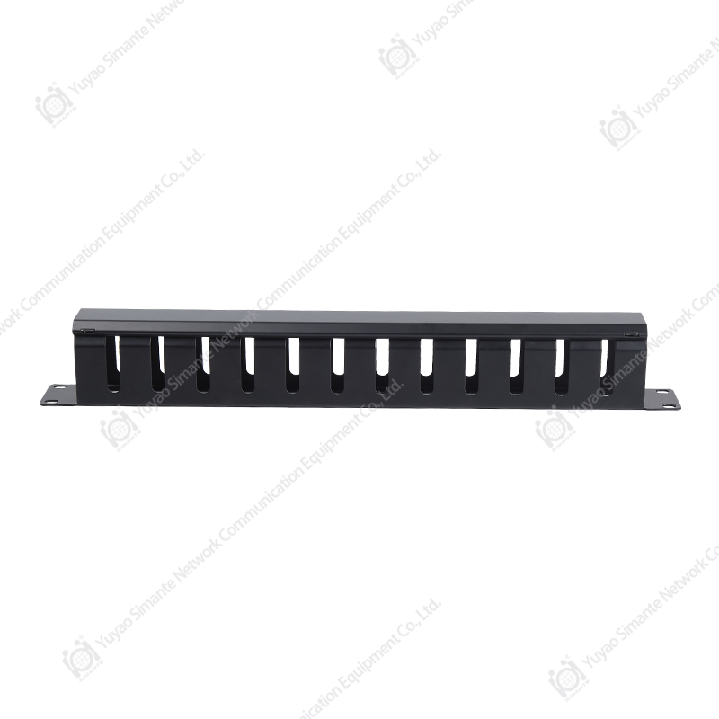
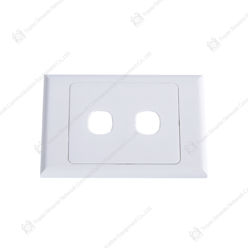
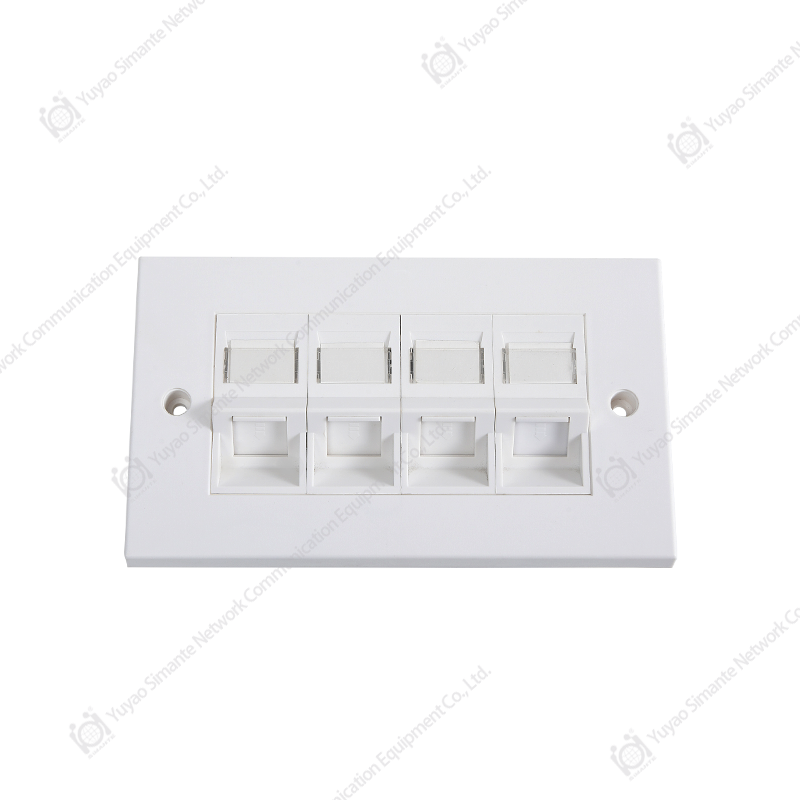
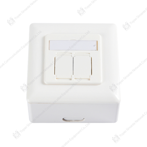
At the outlet, the faceplate is the last point where a mistake becomes visible. Port labeling, not conductor color, is what the end user actually sees, so the labeling scheme deserves the same discipline as the wiring scheme. A faceplate that accepts a printed label insert and holds it firmly is a small feature that pays for itself during every move-add-change that follows. Cable managers and dressing accessories play a supporting role here by keeping bundles ordered, which makes it far easier to trace a single pair back to its source when something does go wrong.
Read the printed guide on the panel and the jack, not your memory. The color chart on the hardware is there because the same four pairs can be arranged in more than one way.
Verification: Proving the Color Code Before Handover
A simple continuity tester proves that eight conductors are connected end to end. It does not prove that they are connected to the right contacts, and it cannot see crosstalk, return loss or delay skew. For permanent links in a commercial project, a handheld certifier that produces a wire map plus performance results is the minimum acceptable evidence, and the report should be archived with the as-built drawing.
Before the tester even comes out, a short visual pass catches most of what matters. The habits worth building into a crew routine look like this:
- Confirm the scheme printed on the panel matches the scheme printed on the jack before terminating anything.
- Check that both conductors of each pair sit in adjacent contact positions and are not separated by a conductor from another pair.
- Keep the untwisted section at the termination point short, typically within about 13 mm.
- Verify that the jacket extends into the strain relief and that no conductor is nicked or scored.
- On shielded work, confirm the drain wire terminates to the housing rather than to a signal contact.
- Label both ends at the same time, not later, and use the same identifier in the drawing and on the outlet.
- Run a wire map test on every link, not on a sample, before the ceiling closes.
Retesting after handover is expensive in a way that is easy to underestimate. Access to a ceiling void, a schedule disruption and a re-certification visit can cost many times the value of a single jack. That imbalance is the whole argument for treating the color code as a controlled process rather than a personal preference.
Test every link with a wire map and a performance report. A continuity buzzer confirms that copper is connected, not that the color code was read correctly.
What to Ask a Manufacturer or Supplier Before Ordering in Volume
When a project moves from hundreds of components to tens of thousands, the questions shift. Price per unit still matters, but the cost of a single inconsistent batch is far higher than the difference between two quotations. Buyers evaluating a manufacturer, supplier or wholesaler for structured cabling hardware usually get the most value from a short, specific list of questions.
- Is the color guide on the keystone jack and patch panel printed for one scheme, or for both, and is it molded or applied as a label?
- How consistent is the jacket printing across production batches, and can samples be drawn from more than one batch for comparison?
- What contact plating is used, and what is the expected mating cycle count under normal field conditions?
- Which third-party performance reports are available for the specific category being quoted, and are they issued for the exact part number?
- Is private labeling or custom packaging available, and what is the minimum order quantity for a customized run?
- What is the typical lead time for repeat orders, and how is that affected by custom tooling or non-standard colors?
Color consistency deserves more attention than it usually gets. A batch of cable whose white-stripe conductor is slightly creamier than the previous batch is not a defect in isolation, but it becomes one when a crew has to judge a stripe under a work light at the far end of a corridor. Manufacturers who control their own extrusion and assembly are generally better positioned to keep that consistency, because the variables sit inside their own process rather than across several subcontractors.
It is also worth asking how the supplier handles mixed-category orders. A project may need CAT5E jacks for voice and CAT6A jacks for data uplinks, and both will be terminated by the same crew on the same day. If the color guides on the two product families are laid out differently, that is a training problem created by the supplier. A coherent product family that uses one consistent visual language across categories removes that risk at no extra cost.
Batch-to-batch color consistency and a legible, consistent printed color guide across the whole product family matter more on large projects than a small difference in unit price.
FAQ: Copper Cable Color Code Questions Installers Ask Most
Is T568A or T568B the correct copper cable color code?
Both are correct and both are defined by the same standards. Neither performs better than the other when applied consistently. The practical answer is to use whichever scheme the project specification names, and if the specification is silent, choose one and apply it to every link on the site.
What happens if one end of a link is T568A and the other is T568B?
The link becomes a crossover. Pins 1 and 2 are exchanged with pins 3 and 6, so signals arrive on different pairs than they left on. Some equipment compensates automatically and some does not, but either way the installation no longer matches the drawing, and a certification test will normally flag the pair arrangement.
How much untwisted conductor is acceptable at the termination point?
Field practice generally keeps the untwisted section within about 13 mm at the contact. Longer untwisted sections raise near-end crosstalk and degrade return loss, and the effect grows as the cable category rises because the twist rates are tighter in higher-performance cable.
What is the color code for a 25-pair copper cable?
It uses five tip colors, white, red, black, yellow and violet, crossed with five ring colors, blue, orange, green, brown and slate, producing 25 unique pairs. Each group of five pairs is wrapped in a colored binder, and the binder colors repeat the same five-color sequence for larger cables.
Do shielded cables use a different color code?
No. Shielded twisted pair cable uses the same four-pair color assignment as unshielded cable. What changes is the presence of a foil or braid shield and a drain wire, which must be terminated to the connector housing rather than to a signal contact.
Can I mix CAT5E and CAT6 components in the same link?
Physically they usually connect, and the color codes are compatible, but the channel performance is limited by the lowest category in the run. A CAT6 cable terminated on a CAT5E jack and connected to a CAT5E patch panel will not certify as a CAT6 channel, regardless of how carefully the colors are matched.
Why does my wire map test show split pairs when the colors look correct?
Split pairs almost always mean that two conductors from different pairs were terminated as if they belonged together. This typically happens when one end of the link follows a different scheme from the other, or when a jack is read from the wrong side. The colors on the insulation can look entirely reasonable while the pairing is wrong.
Every color code question comes back to two rules: keep each pair together on adjacent contacts, and apply the same scheme at both ends of the link.
Bringing It Together: Standardize, Label, Verify
The copper cable color code is one of the few parts of a structured cabling project that can be made completely error-proof with almost no extra cost. It requires a decision, a drawing and a habit, and it removes an entire category of rework from the schedule.
Start by choosing the scheme the specification calls for, or choose one deliberately if the specification is silent. Write it on the as-built drawing and on the inside of the first faceplate. Confirm that the panel label and the jack label use the same visual layout, so an installer reads the same pattern in both places. Keep the untwisted section short, keep the pair intact from end to end, and label both ends during termination rather than afterward.
Then verify. A wire map test on every link before handover is the cheapest insurance available, and it is the only reliable way to prove that the code was read correctly at both ends of every run. Do those three things, and the next telecom room handover will not end with a single failed link at four in the afternoon.
Standardize the scheme, make the color guide legible on every component, and test every link. Those three steps resolve nearly every copper cable color code problem before it reaches the schedule.
Related Resources
Two further references on this site are useful if you are planning a full structured cabling rollout rather than a single link repair.
- Company background and manufacturing capability at Simante, covering the copper and fiber product lines, factory capacity and customization options for volume projects.
- What data encoding technology powers copper cabling systems, a background piece on how signaling schemes interact with the physical layer you have just terminated.