Español
 عربى
عربى русский
Content
- 1 What a Patch Panel Does Inside a Structured Cabling System
- 2 Cat6 Patch Panels vs Fiber Optic Patch Panels: Key Differences
- 3 Why 24 Port Patch Panels Are the Most Common Configuration
- 4 Structured Cabling System Component Breakdown
- 5 Growth Trend in Structured Cabling and Fiber Adoption
- 6 Isometric View of a 24 Port Patch Panel
- 7 Selecting a Reliable Patch Panel Manufacturer
- 8 Frequently Asked Questions
Patch panels are the central connection point of any structured cabling system, and choosing between cat6 patch panels and fiber optic patch panels depends primarily on required bandwidth, transmission distance, and future scalability. For most enterprise office and data closet deployments, a 24 port patch panel using cat6 copper terminations delivers reliable gigabit performance at practical cost, while fiber optic patch panels are the preferred choice when a network must support longer backbone runs, higher immunity to electromagnetic interference, or higher bandwidth growth over the next decade. This guide explains how patch panels function within a structured cabling system, compares cat6 and fiber optic patch panel options in detail, and provides practical guidance for network cabling solution planning, including port density selection, rack layout, and long term scalability planning for manufacturers, wholesalers, integrators, and IT procurement teams.
Structured cabling system design has become increasingly standardized around modular patch panel products, keystone jack termination, and clearly labeled faceplate systems, all of which reduce downtime during moves, adds, and changes. Below, we walk through the technical fundamentals, present data visualizations comparing patch panel configurations, and answer the most common questions asked by facility managers and network installers.
What a Patch Panel Does Inside a Structured Cabling System
A patch panel is a passive hardware unit mounted in a rack or wall enclosure that provides a fixed termination point for horizontal cabling runs coming from work areas, while short patch cords connect the front ports to active network equipment such as switches. This separation between the permanent cable run and the flexible patch cord is one of the foundational principles described in the ANSI/TIA-568 structured cabling standard, which recommends that horizontal cabling be terminated at a patch panel rather than spliced or extended directly to equipment. Using patch panels instead of direct cable-to-switch connections significantly reduces the risk of damaging expensive switch ports because any wear from repeated plugging and unplugging is absorbed by the patch panel and low-cost patch cords instead of the switch hardware itself.
Patch panels are typically categorized by port count, connector type, and cable category. Cat6 patch panels use RJ45 style ports rated to support cat6 performance specifications, including bandwidth up to 250 MHz, while fiber optic patch panels use LC, SC, or ST style adapters to terminate optical fiber strands. A 24 port patch panel is one of the most widely deployed configurations because it fits standard 1U rack space and matches common 24-port switch density, simplifying one-to-one cable management between patch panel ports and switch ports.
- Termination point: patch panels anchor horizontal cabling runs so cross-connects can be made cleanly at the rack.
- Cable management: numbered ports and labeling reduce troubleshooting time in a network cabling solution.
- Protection of active equipment: patch cords absorb wear instead of switch ports.
- Scalability: modular patch panel products allow a rack to grow port by port as the network expands.
Cat6 Patch Panels vs Fiber Optic Patch Panels: Key Differences
Cat6 patch panels and fiber optic patch panels are not interchangeable, and the right choice depends on the specific segment of the network being built. Cat6 patch panels are generally selected for horizontal cabling within a single floor or building, where copper cable runs stay within the 100-meter distance limit defined by the TIA-568 standard for twisted pair cabling. Fiber optic patch panels, by contrast, are selected for backbone links between floors, buildings, or data center rows, where longer distances and higher long-term bandwidth headroom are required.
| Attribute | Cat6 Patch Panel | Fiber Optic Patch Panel |
|---|---|---|
| Connector type | RJ45 | LC / SC / ST adapters |
| Typical distance limit | Up to 100 meters | Multiple kilometers depending on fiber type |
| EMI resistance | Moderate | High |
| Common port counts | 24 port, 48 port | 12, 24, 48 fiber positions |
| Typical use case | Horizontal cabling to work areas | Backbone and riser links |
The radar chart below compares cat6 patch panels and fiber optic patch panels across five practical selection criteria that network cabling solution planners commonly weigh against each other. It visualizes relative strengths rather than exact numeric benchmarks, since actual performance depends on fiber grade, copper category, and installation quality. Reading the chart from the center outward, a larger shaded area along any axis indicates a stronger relative advantage for that attribute. This comparison is intended to help engineers and procurement teams decide which patch panel type fits a given segment of their structured cabling system. The five axes shown are bandwidth headroom, transmission distance, EMI immunity, installation simplicity, and long-term scalability.
As the chart shows, fiber optic patch panels extend further along the bandwidth, distance, and EMI immunity axes, which reflects the physical properties of optical transmission compared to copper. Fiber does not carry electrical current, so it is inherently immune to electromagnetic interference from motors, lighting ballasts, or nearby power cabling, which is why fiber optic patch panels are frequently specified in industrial environments and large campus backbones. Cat6 patch panels extend further along the installation ease axis because RJ45 termination tools and cat6 keystone jack components are widely available and require less specialized training than fiber splicing or polishing. Scalability is roughly comparable between the two panel types at the patch panel level itself, since both are modular by port, though the cabling behind a fiber optic patch panel can typically carry more future bandwidth growth without replacement. For a facility with mixed requirements, it is common to deploy cat6 patch panels for work area connections and fiber optic patch panels for the backbone that ties wiring closets together. This layered approach is consistent with general structured cabling system design principles found in TIA-568 and BICSI reference materials. Distance is the most decisive factor in many projects: once a cable run exceeds the 100-meter copper limit, fiber becomes the practical option regardless of other preferences. Bandwidth headroom matters most for organizations planning multi-year network growth, since re-cabling a backbone is far more disruptive than upgrading active equipment alone. EMI immunity becomes critical in manufacturing plants, elevator shafts, and any pathway running parallel to high-voltage power lines. Installation ease affects total project timeline and the number of qualified technicians needed on site, which matters for wholesalers and integrators managing multiple simultaneous rollouts. In practice, most structured cabling projects use both patch panel types together rather than choosing exclusively one or the other, matching each segment of the network to the medium best suited for its distance and environment.
Why 24 Port Patch Panels Are the Most Common Configuration
Among patch panel products on the market, the 24 port patch panel is consistently the most widely stocked and installed size for small to mid-size wiring closets. This is largely because most access-layer network switches are manufactured in 24-port or 48-port configurations, so a 24 port patch panel maps directly to a single switch, keeping cable runs organized in clean one-to-one groups. A 12 port patch panel is generally reserved for very small closets or half-rack installations, while 48 port patch panels are used in larger consolidated distribution frames where rack space is limited but port density needs are high.
The horizontal bar chart below illustrates the relative frequency with which different patch panel port counts are specified across typical commercial and light industrial cabling projects, based on general industry deployment patterns commonly referenced in structured cabling planning guides. This is intended as a directional illustration of common practice rather than a precise market survey figure. It demonstrates why manufacturers and wholesalers of network cabling products typically prioritize 24 port patch panel and 48 port patch panel inventory. Reading the chart, longer bars represent configurations that appear more frequently in new wiring closet designs. The chart also highlights why keystone jack and faceplate components are usually sized in matching multiples of 12 or 24 to align with patch panel port counts during procurement.
The chart makes clear that the 24 port patch panel occupies the largest share of typical wiring closet deployments, and this pattern holds across office buildings, schools, retail locations, and light industrial facilities. One key reason is rack unit efficiency: a 24 port patch panel fits neatly into a single 1U rack space, which pairs naturally with a 1U 24-port switch directly above or below it in the rack, minimizing patch cord length and reducing cable clutter. A 12 port patch panel is generally chosen only when the closet serves a very small number of work areas, such as a small retail storefront or a single small office suite, where a full 24 port unit would leave too many unused positions. 48 port patch panels become more attractive in larger main distribution frames where floor space is constrained but total port demand is high, though they require more careful cable management planning because twice as many cables converge on a single rack unit. Fiber optic patch panels with 12 or 24 fiber positions are typically sized to match the number of fiber strands running in the backbone cable, and are less driven by rack unit efficiency than by the specific fiber count purchased for that link. For manufacturers and wholesalers supplying structured cabling products, maintaining strong stock levels of 24 port patch panel units alongside compatible keystone jack cat6 components and faceplate rj45 connector accessories supports the most common project specifications received from integrators. Buyers sourcing patch panel manufacturers for volume projects often standardize on the 24 port format specifically because it simplifies training, spare parts inventory, and future capacity planning across multiple sites. This standardization also makes labeling and documentation easier, since installers become familiar with a consistent port layout across many projects. From a total cost of ownership perspective, using a consistent 24 port patch panel format across a multi-site rollout reduces the complexity of maintaining spare units and patch cords across different site inventories. In short, the popularity of the 24 port patch panel is not arbitrary but reflects a genuine alignment between rack space efficiency, switch port density, and simplified project logistics that recur across countless independent cabling installations.
Structured Cabling System Component Breakdown
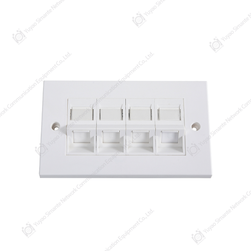
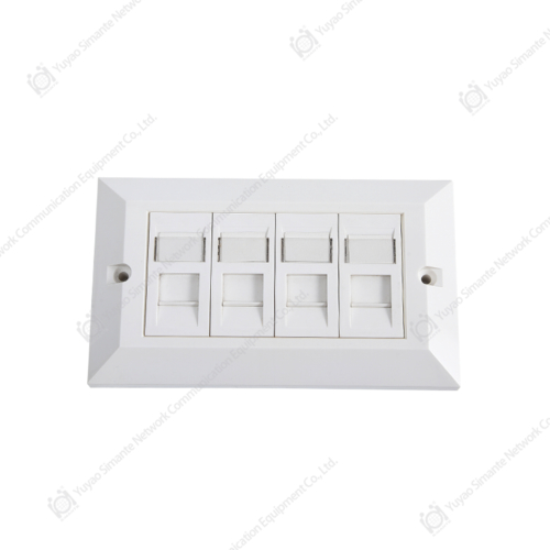
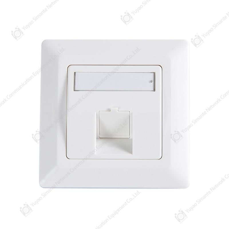
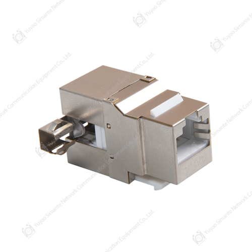
A complete structured cabling system is built from several interdependent structured cabling system components, and patch panels are only one part of this larger assembly. On the work area side, a faceplate houses one or more keystone jack modules, which terminate the horizontal cable at the outlet end. On the equipment room side, that same horizontal cable terminates into a port on the patch panel, and a short patch cord then links the patch panel port to the corresponding switch port. Consistent component selection across faceplate, keystone jack cat6 modules, and patch panel ports is important for maintaining uniform category-rated performance end to end.
The donut chart below illustrates a general breakdown of how physical components are typically distributed across a standard structured cabling system component list for a mid-size office deployment. This distribution is presented as a general planning reference rather than an exact universal ratio, since actual component counts vary by building layout and work area density. It is useful for network cabling solution planners estimating bill-of-materials proportions before finalizing a procurement order. The chart groups components into four broad categories: patch panel units, keystone jack and faceplate combinations, patch cords, and cable management accessories. Reading the chart, each colored segment represents the approximate share of total component units in a typical deployment, not their cost share.
Keystone jack and faceplate combinations typically make up the largest share of physical unit count in a structured cabling system because every single work area outlet requires its own jack and faceplate, while a single patch panel serves dozens of those outlets at once. This is why patch panel unit count is comparatively small relative to total jack count, even though the patch panel is often considered the central hub of the closet. Patch cords represent roughly a quarter of total component count in most deployments, since each active connection requires one patch cord at the panel end and often a second short cord at the equipment end. Cable management accessories, including horizontal cable managers and vertical cable managers, make up the smallest physical unit share but play an outsized role in keeping a rack serviceable over its lifetime. This proportional breakdown helps explain why keystone jack manufacturers and patch panel manufacturers alike see strong steady demand for jack and faceplate products relative to patch panel units themselves, since jack consumption scales directly with the number of work area outlets in a building. For network cabling solution providers assembling bill-of-materials estimates, this rough distribution offers a useful starting point before adjusting for specific floor plans. It also illustrates why matching keystone jack cat6 quality to the patch panel rating is essential, since a weak link anywhere in the chain, from faceplate rj45 connector to jack to patch panel port, can constrain overall channel performance. A structured cabling system is only as strong as its weakest certified component, which is a principle repeatedly emphasized in TIA-568 channel certification testing procedures. For B2B buyers evaluating patch panel manufacturers and keystone jack manufacturers as suppliers, requesting matched category ratings across the full component chain, rather than sourcing components independently from mismatched suppliers, helps avoid certification failures during commissioning. This component-level view also supports more accurate wholesale ordering, since procurement teams can estimate keystone jack and faceplate quantities as a multiple of planned work area outlets rather than guessing at ratios after the fact.
Growth Trend in Structured Cabling and Fiber Adoption
Demand for structured cabling products, including both cat6 patch panels and fiber optic patch panels, has grown steadily as data traffic requirements across offices, data centers, and industrial facilities have increased year over year. Industry cabling reports have repeatedly noted a gradual shift toward higher category copper cabling and greater fiber optic penetration in backbone applications, driven by rising bandwidth demand from cloud computing, video conferencing, and IoT device density. This trend directly affects patch panel specification, since networks built with future bandwidth headroom in mind tend to favor fiber optic patch panels for backbone segments even when copper remains dominant at the work area.
The line chart below presents a general directional trend illustrating how fiber optic patch panel adoption has increased relative to copper-only cabling architectures over a multi-year period, based on commonly cited structured cabling industry growth patterns. The exact figures are illustrative of a general upward trend rather than an exact market statistic, and readers evaluating a specific project should consult current supplier data for precise figures. This chart is useful for network cabling solution planners considering whether to future-proof a backbone with additional fiber capacity now rather than later. The horizontal axis represents time in a general multi-year progression, while the vertical axis represents relative adoption share. The rising line demonstrates a consistent upward trajectory in fiber-based backbone architecture over the period shown.
The upward slope of this line reflects a broader shift in backbone cabling philosophy, where organizations increasingly treat fiber optic patch panels as a standard rather than a premium option for inter-floor and inter-building links. One driver behind this trend is the growing number of connected devices per work area, which increases aggregate bandwidth demand at the switch uplink level even when individual desktop connections remain copper-based. Another driver is the falling relative cost of fiber optic patch panel hardware and pre-terminated fiber assemblies compared to a decade ago, which has made fiber a more accessible option for mid-size deployments, not just large enterprise data centers. As buildings are renovated or expanded, network designers increasingly install fiber optic patch panels between distribution frames even in projects that otherwise use cat6 patch panels at the work area level, creating a hybrid structured cabling system that balances performance and practicality. This hybrid approach also future-proofs backbone segments against bandwidth growth, since replacing a backbone after initial construction is far more disruptive and costly than installing adequate fiber capacity upfront. For companies manufacturing or distributing structured cabling system components, this trend supports maintaining strong production and inventory capability across both categories, cat6 patch panels for horizontal cabling and fiber optic patch panels for backbone applications, rather than specializing narrowly in one medium. Facilities that anticipate future high-density wireless access point deployment, video surveillance expansion, or additional IoT sensor networks often specify additional backbone fiber capacity today specifically to avoid a second disruptive cabling project later. This pattern is consistent with general recommendations found in structured cabling design guides published by cabling standards bodies, which encourage designing backbone capacity for medium-term growth rather than only current-day requirements. For network cabling solution providers, tracking this adoption trend helps align product development and stock planning with where customer demand is heading, rather than only where it has been historically. Overall, while cat6 patch panels remain the dominant choice for individual work area connections due to cost efficiency and simplicity, the structural trend toward greater fiber optic patch panel usage in backbone applications appears likely to continue as bandwidth requirements keep rising across nearly every building type.
Isometric View of a 24 Port Patch Panel
To illustrate the physical layout of a typical 24 port patch panel, the diagram below shows an isometric schematic view highlighting the front port row, rear termination area, and rack mounting ears common to this product category. This type of unit is generally constructed from a steel or aluminum faceplate frame with modular RJ45 ports arranged in one or two rows across the front face. The rear side of the panel typically provides 110-style or krone-style termination points where the horizontal cable conductors are punched down during installation. Cable management bars are frequently included along the top or bottom edge to guide horizontal cabling neatly into the rack without excessive bend radius.
This kind of schematic view is useful for installers unfamiliar with rack layout, since it clarifies which side of the patch panel faces the technician during daily patching work versus which side faces the cable bundle during initial termination. Proper orientation matters because rear termination work is typically done once during installation, while the front port row is accessed repeatedly over the life of the network for moves, adds, and changes. Understanding this layout also helps when planning rack unit spacing, since sufficient vertical clearance should be left above and below each patch panel for patch cord bend radius and cable manager access.
Selecting a Reliable Patch Panel Manufacturer
When sourcing from patch panel manufacturers for a wholesale or project-based order, buyers typically evaluate several practical factors beyond the base specification sheet. Consistency of port alignment and connector quality across production batches matters for large orders, since even small manufacturing variance can complicate rack installation across many identical units. Compatibility with standard keystone jack cat6 modules and common faceplate rj45 connector formats is also important, particularly for buyers who source jacks and faceplates from a different supplier than their patch panel manufacturer.
| Criterion | Why It Matters |
|---|---|
| Category rating consistency | Ensures channel-level cat6 performance is achievable end to end |
| Port and jack compatibility | Simplifies mixing patch panel, keystone jack, and faceplate sourcing |
| Production capacity | Supports large wholesale or multi-site rollout timelines |
| Engineering support | Helps resolve custom port layout or labeling requests |
Yuyao Simante Network Communication Equipment Co., Ltd. is a professional manufacturer of network cabling solutions and optical fiber products integrating design, development, sales and service. In nearly 20 years of service, the company has focused on meeting customer requirements through technical expertise across structured cabling system components, including patch panel products, keystone jack modules, and faceplate assemblies. Based on a mature research and development system, product quality stability is addressed starting at the design stage itself. The company maintains a technical team of more than 10 engineers and over 30 full-time technical personnel who continue to provide professional support in quality improvement and ongoing product development for both cat6 patch panels and fiber optic patch panels.
Frequently Asked Questions
| Q1: What is the difference between a cat6 patch panel and a fiber optic patch panel? A cat6 patch panel terminates copper twisted pair cabling using RJ45 ports for horizontal runs, while a fiber optic patch panel terminates optical fiber strands using LC, SC, or ST adapters, typically for backbone or longer-distance links. |
| Q2: Why is a 24 port patch panel the most common size? A 24 port patch panel fits standard 1U rack space and matches common 24-port switch configurations, making cable management and rack layout simpler for most wiring closets. |
| Q3: Can cat6 patch panels and fiber optic patch panels be used in the same structured cabling system? Yes, many structured cabling systems use cat6 patch panels for work area connections and fiber optic patch panels for backbone links between floors or buildings within the same network cabling solution. |
| Q4: What should buyers check when comparing patch panel manufacturers? Buyers generally review category rating consistency, port and keystone jack compatibility, production capacity, and available engineering support before selecting a structured cabling system component supplier. |